background image

www.avenview.com 

10 


1.9


Software Installation and Setup 


1.9.1


System Requirements 

1.


The  DVI-SPLITPRO-4 provides a  software control program  which  runs under Microsoft  Windows 98, 
2000, XP through the interface of RS-232 serial control. 

2.


Before you click  on the icon of the software, make sure you have secured the connection between 
your computer COM port and the DVI-SPLITPRO-4.   

3.


The DVI-SPLITPRO-4 provides software control. To make sure all information shown in the software is 
synchronized with those in the device, please click “Update” button to acquire the latest data from 
the DVI-SPLITPRO-4 after you press any key on the remote control. 


1.9.2


Software Connection 

1.


Power  up  the  DVI-SPLITPRO-4  and  you  can  see  both  Red  and  Green  LEDs  on  the  front  panel  blink. 
Ensure that Serial RS232 connection is secure.


2.


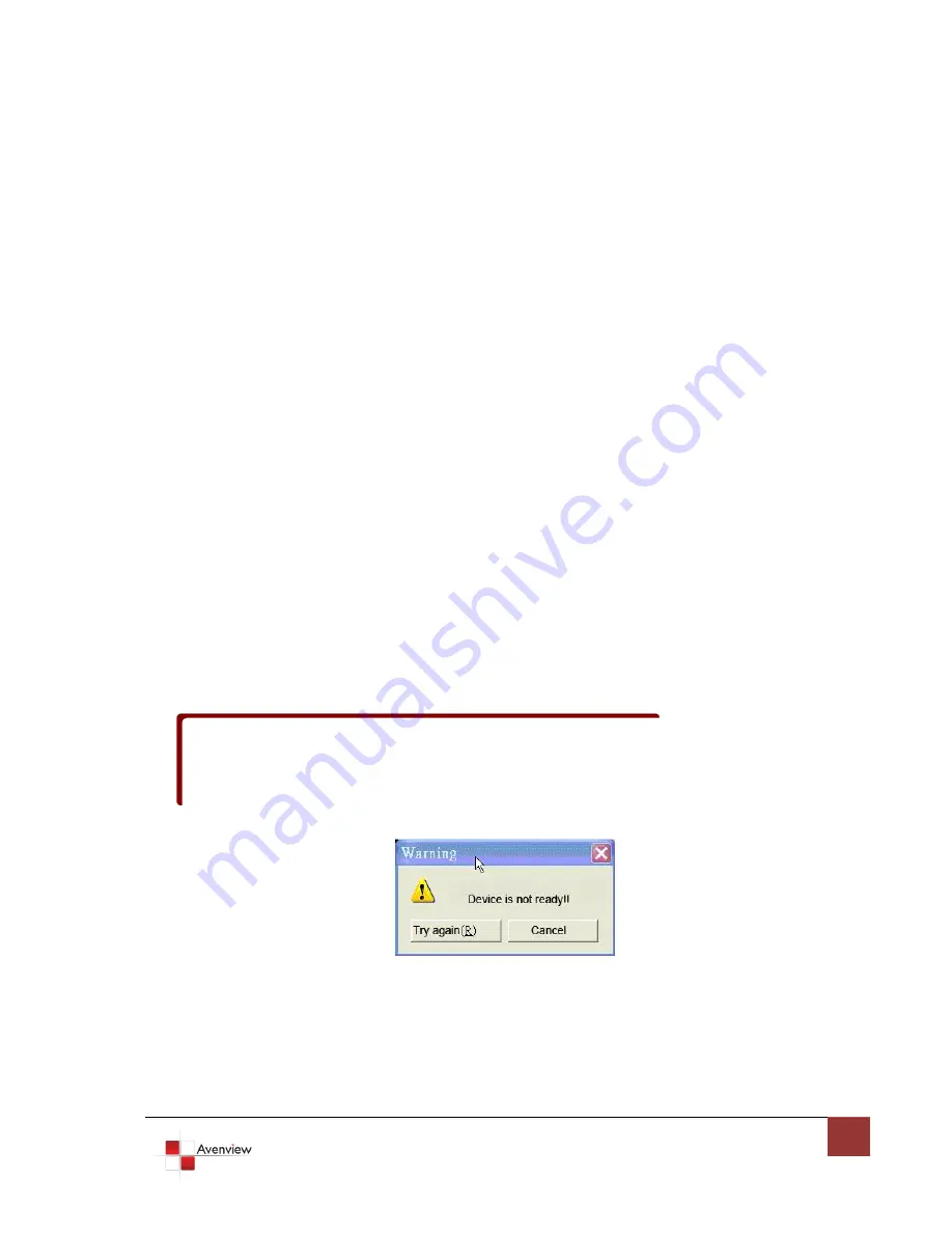
The first step after running the software is to automatically detect if the device responses correctly 
through  RS-232  port.  The  process  takes  5-15  seconds.  If  the  device  is  not  connected,  a  warning 
window will show up.


First of all, choose the correct COM port from the Com Port selection list. Then, 

click  on  the  linkage  button  to  open  the  COM  port.  If  the  specified  COM  port  is  not  available,  the 
“Device  is  not  ready.  Do  you  want  to  try  again?”  error  message  will  pop  up.  Please  check  the 
availability of COM Port. After the COM port is accurately established, please click on status update 
button.


3.


If the serial connection is established, you will see a Windows as shown below: 


If” device is not ready” error pops up then: 

-

Ensure that DVI-SPLITPRO-4 is powered on. 

-

Please ensure that serial cable (RS232) is connected properly and available serial 
port is free to be used by DVI-SPLITPRO-4 


Summary of Contents for DVI-SPLITPRO-4

Page 1: ...t any time without notice No license whether express implied or otherwise to any intellectual property rights is granted by this publication Except as set forth in Avenview Standard Terms and Conditio...

Page 2: ...Installation 6 1 7 Panel Description 7 1 7 1 DVI SPLITPRO 4 Rear Panel 7 1 7 2 DVI SPLITPRO 4 I O Connectors 8 1 8 Installation 9 1 9 Software Installation and Setup 10 1 9 1 System Requirements 10 1...

Page 3: ...fety Instructions The Avenview DVI SPLITPRO 4 Quad Image Video Processor has been tested for conformance to safety regulations and requirements and has been certified for international use However lik...

Page 4: ...nput sources to match the native resolution of monitors flat panel displays projectors as well as user selectable output settings up to WUXGA 1920x1200 Dual outputs are provided in both analog VGA and...

Page 5: ...he converter please check the package contents DVI SPLITPRO 4 x 1 DVI DVI VGA breakout Cable x 4 VGA to Component breakout Cable x 3 DVI to VGA Adapter x 3 DVI to DVI Cable x 2 Rack Mounting Kit x 1 R...

Page 6: ...cause an injury or malfunction Don t place the product in too high temperature over 50 C too low temperature under 0 C or high humidity Use the DC power adapter with correct specifications If inapprop...

Page 7: ...respectively You can pick up four of the ten inputs and then display four of them simultaneously on the same screen Following figure shows the rear panel connectors of a DVI SPLITPRO 1 7 1 DVI SPLITPR...

Page 8: ...to VGA Adapter and VGA to Component Adapter 1 x DVI 1 x VGA DVI to DVI VGA Y Cable 1 x DVI 1 x Component DVI to DVI VGA Y Cable and VGA to Component Adapter VGA VGA Composite Composite with a RCA Cab...

Page 9: ...s PC to the DVI connector of the breakout cable 6 Connect a device equipped with the component video output to 3 RCA jack of the Component video adapter 7 Connect a device with VGA output such as lapt...

Page 10: ...e front panel blink Ensure that Serial RS232 connection is secure 2 The first step after running the software is to automatically detect if the device responses correctly through RS 232 port The proce...

Page 11: ...www avenview com 11 1 9 3 Software Operation The software has following menu options available 1 2 3 4 6 5...

Page 12: ...ctionality of this button is to expedite the default quad display Please note that the input sources will not change Only positions and sizes will be affected 5 Display Area Number There are totally 4...

Page 13: ...input sources for the corresponding display area 2 The chosen input will become blue to indicate current selection 3 Saves parameters for each channel 4 Auto configuration for VGA inputs 5 Color bala...

Page 14: ...gnal 1 2 Volts peak peak ESD Protection Human body model 15kV air gap discharge 8kV contact discharge Input 1 x VGA 3 x DVI 3 x Composite 1 x RS232 1 x RS485 Output 1 x DVI DVI Connector Type DVI I 29...

Page 15: ...640x480 72Hz VESA 640x480 75Hz VESA 640x480 85Hz VESA 800x600 56Hz VESA 800x600 60Hz VESA 800x600 72Hz VESA 800x600 75Hz VESA 800x600 85Hz Supported Mode Resolution MAC 832x624 75Hz VESA 1024x768 60Hz...

Page 16: ...to split your video source into to images displayed on two different screens That will lower output video quality Use a distribution amplifier instead of T connectors Make sure the video source is no...

Page 17: ...A solid UTP CAT5e cable shows longer transmission length than stranded STP CAT6 cable For long extension users solid LAN cables are your only choice 4 EIA TIA 568 B termination T568B for LAN cables is...

Page 18: ...atory profits or for punitive incidental or consequential damages in connection with the furnishing performance or use of the Avenview hardware software or other products and documentation provided he...

Reviews: