background image

4x4 HDMI 2.0 Matrix Kit 

16 

6.2 IR Pass-through Control 

The matrix supports bi-directional IR pass-through, allowing the devices can be 
controlled by both source and destination ends. This section provides connection and 
switching examples to illustrate possible configurations.   


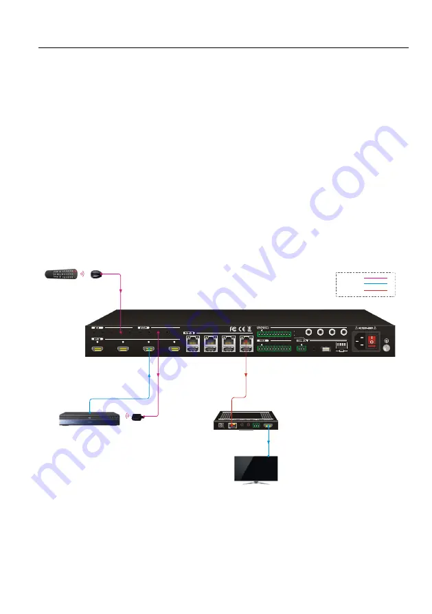
6.2.1 Control Local Input Device from Local 

By default, there is a one-to-one correspondence between the IR OUT port on the 
matrix and the HDMI input. When switch an HDMI input, the corresponding IR OUT will 
be switched synchronously.   


Example: Switch HDMI input 3 to HDBaseT output 4.   

Connect an IR receiver to the 

IR IN 4 

port, and an IR Emitter to the 

IR OUT 3 

port, the 

connection diagram shown as below: 


4K Blu-Ray

4

1

2

3

4

L

R

1

2

3

4

H

D

B

a

s

e

T
H

D

M

I

1

2

3

4

Tx

Rx

1

2

3

4

1

2

3

4

ALL IN

1

2

3

4

ALL OUT

IR EYE

RS232

Tx

Rx

TCP/IP

Input 
De-embedded

Output 
De-embedded

FW

1

2

3

IR Emitter

IR Receiver

Remote

Receiver

Display

HDMI:

IR:

HDBaseT:

Summary of Contents for GeMNeXT Matrix-4X4-HBT-H2-KIT

Page 1: ...USER MANUAL Matrix 4X4 HBT H2 KIT 4x4 HDMI 2 0 Matrix Kit All Rights Reserved Version Matrix 4X4 HBT H2 KIT_2018V1 4...

Page 2: ...tatement This equipment generates uses and can radiate radio frequency energy and if not installed and used in accordance with the instructions may cause harmful interference to radio communications I...

Page 3: ...re or install this product near water Do not put any heavy items on the extension cable in case of extrusion Do not remove the housing of the device as opening or removing housing may expose you to da...

Page 4: ...r Panel 8 4 System Connection 9 4 1 Usage Precaution 9 4 2 System Diagram 9 5 Button Control 10 5 1 Signal Switching 10 5 2 EDID Management 11 5 3 Inquiry Mode 13 5 4 Recall Preset 14 6 IR Control 15...

Page 5: ...Third party Device from Local 37 8 1 4 Control the Local Third party Device from Remote 38 8 2 RS232 Control Software 39 8 3 RS232 Commands for Controlling Matrix 40 8 3 1 System Command 40 8 3 2 Sign...

Page 6: ...trol and transmission which could be used in a number of different installation scenarios for example with computers for monitoring purposes large screen displays conference systems television educati...

Page 7: ...with 4 Screws 1x IR Receiver 1x IR Remote 1x 3 pin to DB9 RS232 Cable 9x 3 pin RS232 Terminal Blocks 1x Power Cord HDBaseT Receiver 4x HDBaseT Receivers 8x Mounting Ears with 8 Screws 16x Plastic Cus...

Page 8: ...l audio Output Connector 4 3 pin terminal blocks 4 Coaxial jacks Output Analog Audio Format PCM Output Digital Audio Format PCM Audio Output Impedance 70Ohms Frequency Response 20 Hz to 20 kHz 3dB Com...

Page 9: ...1 IR IN 1 IR OUT 1 RS232 Control Connector 2 3 5mm mini jacks 1 3 pin terminal block General Resolution Range Up to 4K 2K 60Hz 4 4 4 Bandwidth 18Gbps Transmission Mode HDBaseT Transmission Distance 10...

Page 10: ...serves as UP navigation button OUTPUT Four buttons for output channel selection Button 2 3 and 4 also serve as LEFT DOWN and RIGHT navigation buttons Menu buttons CLEAR Cancel the current commands if...

Page 11: ...eivers OUTPUT Four HDBaseT RJ45 outputs to connect the four HDBaseT receivers four local HDMI ports to connect local displays AUDIO OUT Four 3 pin terminal blocks for analog audio output Four coaxial...

Page 12: ...GROUND Connect to earth to ensure the unit is well grounded 3 3 Receiver Front Panel Switch to select the RS232 control mode CTRL RS232 pass through control UPDATE A Connect the RS232 port to the PC...

Page 13: ...connected with control device e g PC and another one should be connected with the third party device IR IN 3 5mm jack to connect IR receiver IR OUT 3 5mm jack to connect IR emitter HDBT IN HDBaseT RJ...

Page 14: ...nsulated and safe All devices should be connected before power on 4 2 System Diagram Receiver Projector Remote IR Receiver IR Emitter 4 1 2 3 4 L R 1 2 3 4 HDBaseT HDMI 1 2 3 4 Tx Rx 1 2 3 4 1 2 3 4 A...

Page 15: ...5 1 Signal Switching Switch an input to an output Operation INPUT OUTPUT ENTER Example Switch Input 1 to Output 2 INPUT OUTPUT Note In default status 4 IR OUT ports correspond with 4 HDMI INPUTS When...

Page 16: ...ENTER Example Input 2 reads EDID data from output 4 INPUT OUTPUT To copy the EDID data from a single output port to all input ports Operation EDID ALL OUTPUT ENTER Example All input ports read EDID da...

Page 17: ...ample Set the EDID data of INPUT 4 to the fourth predefined EDID data type 1080p 3D Hold for 3 seconds INPUT Set a predefined EDID setting for all input port Operation Step1 Press and hold EDID for 3...

Page 18: ...t port and display device Report the signal switching status Report the HDCP compliance of all input ports Y means the input AV signal is transferred with HDCP N means the input AV signal content does...

Page 19: ...Step1 Press RECALL button the LCD screen displays PRESET LOAD Step2 Press LEFT and RIGHT navigation buttons to select PRESET 1 9 Step3 Press ENTER to confirm Example Recall the Preset 1 Step1 Press R...

Page 20: ...ons Output channel selection buttons Menu buttons ALL Select all inputs and outputs EDID Enable input port to manually capture and learn the EDID data of outputs devices CLEAR Cancel the current comma...

Page 21: ...rrespondence between the IR OUT port on the matrix and the HDMI input When switch an HDMI input the corresponding IR OUT will be switched synchronously Example Switch HDMI input 3 to HDBaseT output 4...

Page 22: ...nd an IR Emitter to the IR OUT 3 port the connection diagram shown as below 4K Blu Ray 4 1 2 3 4 L R 1 2 3 4 HDBaseT HDMI 1 2 3 4 Tx Rx 1 2 3 4 1 2 3 4 ALL IN 1 2 3 4 ALL OUT IR EYE RS232 Tx Rx TCP IP...

Page 23: ...Connect an IR Receiver to IR IN port on the receiver then connect an IR emitter to the IR OUT 3 on the matrix The third input source can be controlled through its corresponding IR output port The con...

Page 24: ...ust be connected to the IR IN port on each connected HDBaseT receiver as shown in the diagram below 4K Blu Ray 4 1 2 3 4 L R 1 2 3 4 HDBaseT HDMI 1 2 3 4 Tx Rx 1 2 3 4 1 2 3 4 ALL IN 1 2 3 4 ALL OUT I...

Page 25: ...ut 3 to HDBaseT output 3 Connect an IR Receiver to IR IN 3 port on the matrix then connect an IR emitter to the IR OUT on the receiver as shown in the diagram below 4K Blu Ray 4 1 2 3 4 L R 1 2 3 4 HD...

Page 26: ...ted to the IR OUT port on each connected HDBaseT receiver as shown in the diagram below Receiver Display IR Emitter Receiver Display IR Emitter Receiver Display IR Emitter Receiver Display IR Emitter...

Page 27: ...it 22 7 GUI Control The matrix also be controlled via TCP IP The default IP settings are IP Address 192 168 0 178 Subnet Mask 255 255 250 0 Type 192 168 0 178 in the internet browser it will enter the...

Page 28: ...ich inputs are directed to which outputs For example clicking the button on the Input 1 row and Output 2 column directs input 1 to output 2 Use the 9 numbered buttons under scene area to save and load...

Page 29: ...x Kit 24 7 2 Coaxial Audio Control Click Audio to enter the below section to select the digital audio from HDMI input or HDBaseT output and the audio can be mute or unmute by pressing the volume icon...

Page 30: ...2 0 Matrix Kit 25 7 3 Configuration The configuration section allows to manage HDCP compliance and the EDID settings Click HDCP to enter the below section to turn on off HDCP compliance for every out...

Page 31: ...lick EDID Copy to enter the below section to copy the EDID data from a single output port to input ports Operation 1 Select one output port 2 Select one or several input ports Press ALL to select all...

Page 32: ...Kit 27 Click EDID Setting to enter the below section to set a predefined EDID for input ports Operation 1 Select a predefined EDID 2 Select one or several input ports Press ALL to select all input po...

Page 33: ...EC Control If the input sources HDBaseT output devices and local HDMI output devices support CEC they can be controlled via the following CEC interface Click HDMI Input to enter the below section to c...

Page 34: ...MI 2 0 Matrix Kit 29 Click HDBT Output to enter the below section to control the selected HDBaseT output device Click HDMI Output to enter the below section to control the selected local HDMI output d...

Page 35: ...T port which is connected with HDBaseT receiver which must have third party device attached 2 Set the baud rate 3 Typing the commands in the box to control the selected remote third party device which...

Page 36: ...ix Kit 31 7 6 Access Setting Click Access to enter the below section to reset password and lock or unlock front panel buttons Click Confirm to save any changes or click Cancel to cancel any changes th...

Page 37: ...Kit 32 7 7 Interface Setting Click Interface to enter the below section to modify title bar label LCD readout and button labels Click Confirm to save any changes or click Cancel to cancel any changes...

Page 38: ...rk Setting Click Interface to enter the below section to change the default IP Address Subnet Mask and Gateway setting Static IP or Dynamic Host Configuration Protocol DHCP also can be chosen Click th...

Page 39: ...e and password the same as the GUI log in setting modified password will be available only after rebooting to login the configuration interface After that click Administration in the source menu to ge...

Page 40: ...rol the matrix from a local PC the 3 pin to DB9 RS232 Cable is used to connect between the matrix and PC The connection diagram is shown as below 4 1 2 3 4 L R 1 2 3 4 HDBaseT HDMI 1 2 3 4 Tx Rx 1 2 3...

Page 41: ...below Note The command RemoteCtrMcu x x is 1 or 0 needs to be sent to enable or disable this control mode For example send the command RemoteCtrMcu1 to enable the remote control mode and send the comm...

Page 42: ...matrix with 3 pin to DB9 RS232 Cable then connect a third party device e g projector to the RS232 port of the determined HDBaseT receiver The remote third party device can be controlled by the local...

Page 43: ...eT receiver with 3 pin to DB9 RS232 Cable then connect a third party device e g projector to the corresponding RS232 port of matrix The local third party device can be controlled by the remote PC the...

Page 44: ...PC by an RS232 connection a RS232 control software should be installed in PC Here using CommWatch exe as an example The icon is shown as below Double click the icon to run and its interface is depict...

Page 45: ...DBaseT Matrix Name Report matrix name Name MP44 Lock Lock front panel buttons Lock System Locked Unlock Unlock front panel buttons Unlock System Unlock Version Report software version Version V1 0 0 D...

Page 46: ...Switch input x AV to all output x 1 4 1All 01 To All All Switch all input signal to their corresponding output channel 1 1 2 2 3 3 4 4 All All Through All Switch off all output All All Closed x Switc...

Page 47: ...K Y Y Y Y 9972 Report the connection status of all outputs Y means the corresponding output port is connected to an output device N means not 9972 OUT 1 2 3 4 LINK Y Y Y Y 9975 Report the switching st...

Page 48: ...logAudio03UM AnlogAudio04UM 8 3 5 EDID Configuration Command Description Command Example and Response EDIDH x B y Set the EDID data of output x to input y If the EDID data is available and the audio p...

Page 49: ...input x recall the embedded EDID y x 1 4 y 1 7 1 720p 2D PCM DTS Dolby 2 720p 3D PCM DTS Dolby 3 1080p 2D PCM 4 1080p 3D PCM DTS Dolby 5 4K 30Hz PCM DTS Dolby 6 4K 60Hz 4 2 0 PCM DTS Dolby 7 4K 60Hz 4...

Page 50: ...te Setting To ensure the bi directional RS232 communication the serial baud rate of matrix should be set as the same as the RS232 ports on remote HDBaseT receivers Command Description Command Example...

Page 51: ...ports are 01 04 and the HDBT output ports are 05 08 The HDMI input ports are 01 04 The port is FF for sending command to all input or output ports The command represents the specific command from the...

Page 52: ...EC_IN_01_SEND_SUCCESS CECI port 4B Forward CECI014B CEC_IN_01_SEND_SUCCESS CECI port 4C Backward CECI014C CEC_IN_01_SEND_SUCCESS CECI port 6C Power off CECI016C CEC_IN_01_SEND_SUCCESS CECI port 6D Pow...

Page 53: ...1 2 3 4 HDBaseT HDMI 1 2 3 4 Tx Rx 1 2 3 4 ALL IN 1 2 3 4 ALL OUT IR EYE RS232 Tx Rx TCP IP Input De embedded Output De embedded FW 1 2 3 1 2 3 4 ALL ENTER RECALL CLEAR EDID 1 2 3 4 1 2 3 4 INPUT PWR...

Page 54: ...ction is good EDID management does not work normally The HDMI cable is broken at the output end Change for another HDMI cable which is in good working condition Static becomes stronger when connecting...

Page 55: ...ar Use of supplies or parts not meeting our specifications No certificate or invoice as the proof of warranty The product model showed on the warranty card does not match with the model of the product...

Page 56: ...4x4 HDMI 2 0 Matrix Kit 51 www GeMNeXT com GeMNeXT rights owned by AVDIS B V Tel 31 0 85 2100 614 Email info gemnext com Website www gemnext com Ambachtstraat 3A 3732 CN De Bilt The Netherlands...

Reviews: