background image

6

P

 U T T I N G   I N T O   S E R V I C E

A I R   S U P P L Y

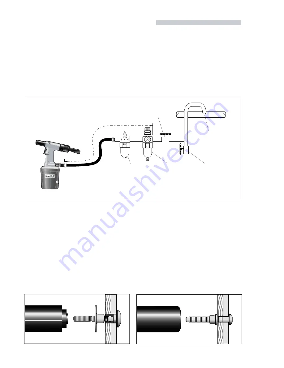
All tools are operated with compressed air at an optimum pressure of 5.4 bar. We recommend the use of pressure regulators and
automatic oiling/filtering systems on the main air supply. These should  be fitted within 3 metres of the tool (see diagram bel ow) to ensure
maximum tool life and minimum tool maintenance.

Air supply hoses should have a minimum working effective pressure rating of 150% of the maximum pressure produced in the system
or 10 bar, whichever is the highest. Air hoses should be oil resistant, have an abrasion resistant exterior and should be armou

red where

operating conditions may result in hoses being damaged.  All air hoses MUST have a minimum bore diameter of 6.4  millimetres or 

1

/

4

  inch.

Read servicing daily details page 10.

8

6

4
2

0

0

1

2

1

4

1

6

1

TAKE OFF POINT

FROM MAIN SUPPLY

STOP COCK

(USED DURING MAINTENANCE 

OF FILTER/REGULATOR OR LUBRICATION UNITS)

MAIN SUPPLY
DRAIN POINT

PRESSURE REGULATOR

AND FILTER

(DRAIN DAILY)

LUBRICATOR

3

ME

TRES MAXIMUM

O P E R A T I N G   P R O C E D U R E

07611 model for AVTAINER

■ 

Ensure that the correct nose assembly is fitted.

■ 

Connect the tool to the air supply.

■ 

Push the Avtainer through the prepared hole in the application.

■ 

Slide the collar over the stem (orientation as shown below).

■ 

Keeping the head of the Avtainer against the application, place the
nose assembly of the tool over the protruding stem.

■ 

Fully operate the trigger. One cycle will ensure that the collar is

forced over the lock grooves of the stem and that the stem breaks
at the breaker groove.

■ 

Release the trigger. The tool completes its cycle by pushing itself off
the collar and ejecting the spent stem at the rear.

07613  model for MAXLOK

■ 

Ensure that the correct nose assembly is fitted.

■ 

Connect the tool to the air supply.

■ 

Push the Maxlok stem through the application hole .

■ 

Place the collar on the stem (orientation as shown below).

■ 

Keeping the head of the stem against the application, push the tool
onto the protruding stem.

■ 

Fully depress the trigger. One cycle will ensure that the collar is

swaged into the lock grooves of the stem and the the stem breaks
at the breaker groove.

■ 

Release the trigger. The tool completes its cycle by pushing itself off
the collar and ejecting the spent stem at the rear.

Summary of Contents for 7611

Page 1: ...Pneumatic Power Tool Pass onto user to read and keep for reference Instruction Manual 0761 type 07611 07613 07614...

Page 2: ...VOLUME REQUIRED 5 4 bar 80 lbf in 2 3 5 litres 0 12 ft 3 STROKE 07611 Minimum 25 4 mm 0 95 in 07613 4 Minimum 17 3 mm 0 68 in PULL FORCE 07611 4 8 bar 70 lbf in 2 10 91 kN 2450 lbf 07613 4 5 4 bar 80...

Page 3: ...U L T D I A G N O S I S General 2 Specific to 0761 Tool 3 Selection Dimensions 4 5 Air Supply 6 Operating Procedure 6 7 Accessories 7 Fitting Servicing Components 8 9 Daily Weekly 10 Service Kit 11 T...

Page 4: ...SHALL BE UNDERTAKENONLYBYPERSONNELTRAINEDINAVDELPROCEDURES DONOTDISMANTLE THISTOOL MACHINEWITHOUT PRIORREFERENCETOTHEMAINTENANCEINSTRUCTIONS CONTACT AVDEL WITH YOUR TRAINING REQUIREMENTS THE TOOL MAC...

Page 5: ...IS FACING AWAY FROM THE OPERATOR AND OTHER PERSON S WORKING IN THE VICINITY WHEN USING THE TOOL THE WEARING OF SAFETY GLASSES IS REQUIRED BOTH BY THE OPERATOR AND OTHERS IN THE VICINITY TO PROTECT AG...

Page 6: ...nd a priming pump is al so included See the Priming section for more details It is also possible to order the base tool only which is supplied without a nose as sembly or a priming pump For more detai...

Page 7: ...1 6 7 0 E P Y T 152 6 114 4 5 321 12 5 20 0 8 7 1 1 6 4 0 1 2 5 2 8 175 6 9 6 9 9 3 4 6 1 0 3 2 9 0 07613 for MAXLOK fasteners Dimensions shown in bold are millimetres Other dimensions are in inches...

Page 8: ...P E R A T I N G P R O C E D U R E 07611 model for AVTAINER Ensure that the correct nose assembly is fitted Connect the tool to the air supply Push the Avtainer through the prepared hole in the applica...

Page 9: ...o fit the stem collector unscrew the end cap and remove together with the stem deflector items9and10ofpage14to17 Assemble the stem collector as shown on the drawing opposite Push the assembly onto the...

Page 10: ...RONT SPRING GUIDE SPRING REAR SPRING GUIDE LOCKING RING ITEM COMPONENT PART N QTY AVTAINER nose assembly 07498 00800 C O M P O N E N T P A R T N U M B E R S 1 2 3 5 6 9 10 11 12 3 5 9 6 10 11 12 3 5 6...

Page 11: ...g guide 6 Screw or drop rear spring guide 10 into chuck collet 3 Fit locking ring 11 onto the jaw spreader housing of the tool item 24 pages 14 to 17 Holding tool pointing down screw the assembled jaw...

Page 12: ...should not be involved in maintenance or repair of the tool unless properly trained D A I L Y Daily before use or when first putting the tool into service pour a few drops of clean light lubricating o...

Page 13: ...le container Prior to dismantling the tool it is necessary to remove the nose assembly For simple removal instructions see the nose assemblies Fitting Instructions page 9 For total tool servicing we a...

Page 14: ...lip 39 using circlip pliers Replace the head retaining plate 3 inside bore Screw nose bullet onto end of piston rod Insert piston seal entry guide into the hydraulic bore Ensuring correct orientation...

Page 15: ...into the handle assembly Fit new gasket 47 If nut 46 is removed it MUST be replaced by a new one Assemble handle to air cylinder and complete assembly in reverse order to dismantling AIR VALVE ASSEMBL...

Page 16: ...F BASE TOOL 07611 00200 24 x a m m m 5 8 x a m 5 3 3 21 20 11 12 13 14 17 49 47 48 18 43 50 51 42 52 45 46 10 23 1 2 3 4 5 6 7 8 16 15 9 A A B B 19 44 30 54 31 55 32 34 33 35 37 38 36 28 29 41 40 58 5...

Page 17: ...SPREADER HOUSING 1 28 07007 00311 SILENCER 1 29 07490 03506 END PLUG 1 30 07340 01303 SPRING 1 2 31 07490 03507 VALVE SPOOL 1 32 07003 00001 O RING 2 4 33 07490 03800 SILENCER BUSH 1 34 07490 03501 S...

Page 18: ...0200 07614 00200 07613 00200 ONLY 27 24 39 20 11 12 13 14 17 49 48 47 18 43 50 51 44 52 45 46 10 23 1 2 3 4 5 6 7 8 9 A A B B 19 42 30 54 31 55 32 34 33 35 37 38 36 28 A 29 A 53 26 25 24 b 41 40 58 59...

Page 19: ...OR 1 27 07614 00201 GUIDE TUBE 1 1 28 07007 00311 SILENCER 1 1 29 07490 03506 END PLUG 1 1 30 07340 01303 SPRING 1 1 31 07490 03507 VALVE SPOOL 1 32 07003 00001 O RING 2 4 33 07490 03800 SILENCER BUSH...

Page 20: ...56 on the side of the head Screw the priming pump into the hole left by screw 41 Actuate the priming pump several times until the air coming out of the bleed screw hole is free of air bubbles Replace...

Page 21: ...joints or replace components Replace Adjust air pressure to within the specification Lubricate tool at air inlet point Fit new jaws Prime tool Service the nose assembly Fit new jaws Service the nose...

Page 22: ......

Page 23: ...owing standards or other formative documents EN292 part 1 and part 2 ISO 8662 part 1 ISO 3744 ISO PREN792 part 14 following the provisions of the Machine Directive 98 37 EEC Welwyn Garden City date of...

Page 24: ...acument com JAPAN Acument Japan Kabushiki Kaisha Center Minami SKY 3 1 Chigasaki Chuo Tsuzuki ku Yokohama city Kanagawa Prefecture Japan 224 0032 Tel 81 45 947 1200 Fax 81 45 947 1205 Email info acume...

Reviews: