


11
M A I N T E N A N C E
Every 200000 cycles the tool should be completely dismantled and components replaced where worn, damaged or when recommended.
All ‘O’ rings and seals should be replaced with new ones and lubricated with Moly Lithium grease EP 3753 before assembling.
I M P O R T A N T
Safety Instructions appear on pages 2 & 3.
The employer is responsible for ensuring that tool maintenance instructions are given to the appropriate personnel. The
operator should not be involved in maintenance or repair of the tool unless properly trained.
The airline must be disconnected before any servicing or dismantling is attempted, unless specifically instructed not to.
It is recommended that any dismantling operation be carried out in clean conditions.
Item
numbers in bold
refer to the General Assembly drawing and parts list (pages 14 and 15).
Prior to dismantling the tool it is necessary to remove the nose assembly. For simple removal instructions see the nose assemblies section,
page 8 and 9.
7572 CLUTCH DETAILS
SPRING
PART Nº
SPRING
COLOUR
1
2
3
4
5
6
7
8
9
10
11
12
13
14
Nº OF TURNS/lb f ins
UNSET CLUTCH
PART Nº
08558-00390
08556-00412
SILVER
08558-00380
08572-00407
OXIDE BLACK
-
-
10 12.5 15 17.5 20 22.5 25
28
31
34
37
-
-
-
5
6
7
8
9
10
11
12
13
14
15
16
CLUTCH
Place housing and bush assembly
51
in vice fitted with soft jaws.
Unscrew clutch housing
2
(left hand thread) and remove bush
1
from clutch housing
2
.
Withdraw the clutch assembly, taking care not to bend push rod
9
. Pull out push rod (long)
9
.
Remove the tool from the vice and gently tap on the front end of assembly to remove needle roller
30
and push rod (short)
33
.
Holding the square drive end of clutch spindle
60
, unscrew adjustment nut
11
.
Pull off adjustment lock washer
10
and spring
8
.
Depress spring
8
and remove pin
61
.
Remove collar
5
and three balls
4
.
Remove split retaining ring halves
6
.
Move front jaw
64
relative to clutch spindle
60
until small hole in side of front jaw
64
is aligned with track of the balls in clutch
spindle
60
.
Ten balls
3
will become visible through small hole in front jaw
64
.
Gently tap front jaw
64
, allowing the ten balls to fall out of hole in the front jaw, (as each ball is ejected, turn front jaw
64
on clutch
spindle
60
to align next ball with hole).
Insert small rod through centre of front jaw
64
and tap out clutch spindle
60
.
Remove drive jaw
63
, key
62
and spring
7
.
Assemble in reverse order to dismantling.
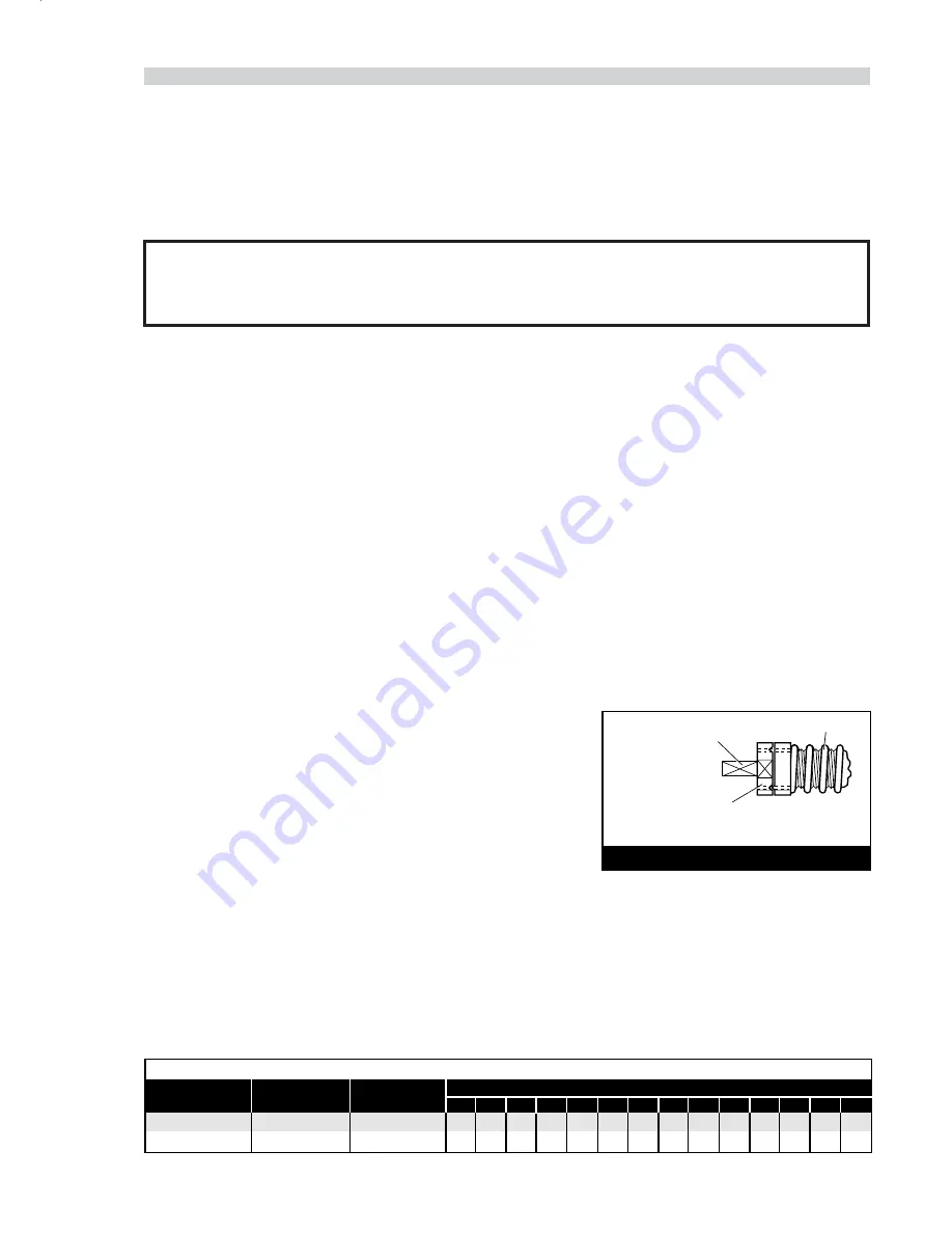
Reset clutch torque in the following manner, (see diagram opposite):
Place square drive on end of clutch spindle
60
in vice, engaging approximately
10 mm in vice jaws. This allows access for spanner entry.
Using the spanner, unscrew adjustment nut
11
until it is level with the end of the
thread of the clutch spindle. Torque can then be increased/decreased as
dictated by fastener type and size by turning the adjustment nut clockwise
anticlockwise as appropriate.
Use the data in the table below to know how many turns give a particular torque.
RESETTING CLUTCH TORQUE
CLUTCH SPRING
SQUARE DRIVE ON END
OF CLUTCH SPINDLE
ADJUSTMENT NUT SET
LEVEL WITH FACE AT END
OF THREAD ON CLUTCH SPINDLE
■
■
■
■
■
■
■
■
■
■
■
■
■
■
■
■
■
■


