


3
Mount
Placing your i120 on a table
To install the i120 as a tabletop unit, you must attach
the provided rubber feet to the underside of the i120.
1. Remove the four feet from the packaging.
2. Turn the i120 upside down.
- Ensure the base of the i120 is clean.
3. Peel the feet off the backing sheet.
4. Position each foot into one of the mounting sites,
near each corner of the i120.
5. Press each foot firmly so that it adheres strongly to
the i120.
Mounting your i120 in a rack
You can mount the i120 in a standard 19-inch rack.
Note
: The i120 can weigh up to 41 pounds (18.7 kg).
Two people may be needed to mount the i120 in the
rack.
You must attach the supplied mounting brackets to the
front or the middle of the i120.
• Ensure that the rack is bolted to the floor and is
earthquake protected, if required. If the rack is not
securely fixed in place, do not continue with the
installation.
• If you are mounting your i120 is in a rack with other
equipment already installed, position the i120 to
avoid imbalance.
You can attach mounting brackets without cable
guides to:
• Each side of the front of the i120, so that the front
of the i120 is flush with the rack.
• The middle of each side panel of the i120, so that
the i120 projects forward from the rack.
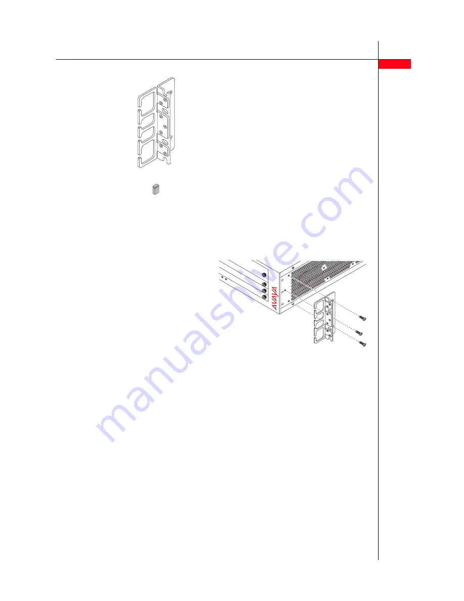
You can attach a mounting bracket with cutouts that
guide cables to the side of the i120. These cutouts
provide easier access to the front panel and help you
manage the placement of the cables.
• To rack-mount the i120 at the front, attach one
regular bracket and the bracket with cable guides.
• To rack-mount the i120 at the middle:
1 Attach two regular mounting brackets on the
sides of the chassis in the mid-mount position
2 Attach the mounting bracket with the cable
guides to the front of the chassis.
One mounting
racket with cable
holder
Jumper for
NVRAM init.
•
Getting Started
with your Distributed
Office i120
, 03-602018 (this document)
•
Troubleshooting Tips for Avaya Distributed Office
,
03-602028.
•
Unleash the Full Potential of Avaya Distributed
Office
, 03-602022.
•
Documentation Map for Avaya Distributed Office
,
03-602021
•
Quick Reference Guide for Avaya Distributed
Office voice mail
, 03-602108.
• Avaya Distributed Office Documentation CD,
03-602138.
• Profiles for Avaya Distributed Office DVD
RST
ASB
i120
Distributed
Of
fice
Summary of Contents for i20
Page 9: ...9 ...


