Avaya CallPilot 1006r Hardware Installation Download Page 36

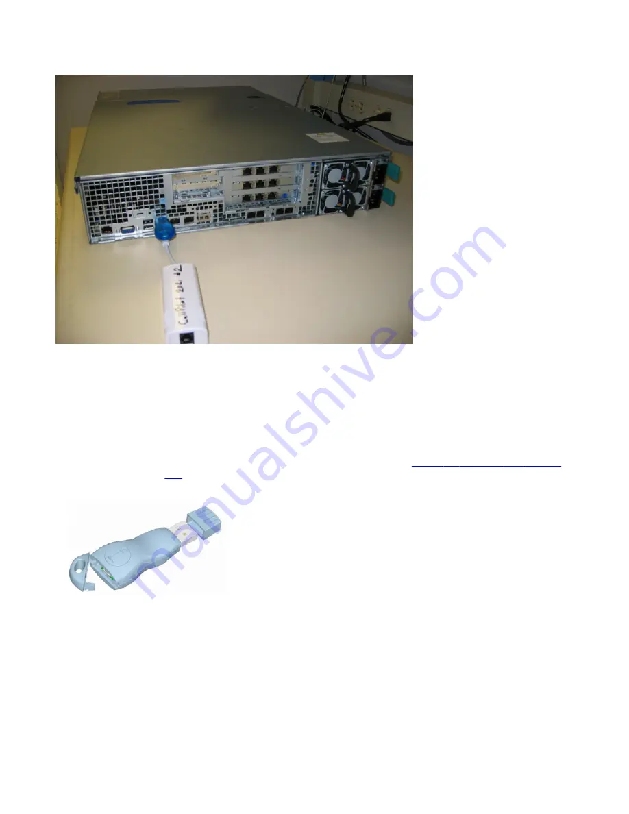
Figure 6: Dongle installed on the server.

To install the software feature dongle

1. Ensure that there is nothing plugged into the upper USB port labeled D on the rear

panel.

2. If the software feature key is not pre-installed in the dongle, insert it into the software

feature slot on the dongle. Insert the software feature key with the data contact

facing down and away from the embossed i. See 

Figure 8: Installing the feature

key

 on page 37.

Figure 7: Dongle without feature key

3. To eject a software feature key, insert a straightened paper clip into the side access

hole.

Push the paper clip in the direction of the software feature key.

Installing the server and peripheral devices

36     Avaya CallPilot® 1006r Server Hardware Installation

December 2010

Summary of Contents for CallPilot 1006r

Page 1: ...Avaya CallPilot 1006r Server Hardware Installation 5 0 NN44200 320 01 03 December 2010...

Page 2: ...OR USING THE SOFTWARE OR AUTHORIZING OTHERS TO DO SO YOU ON BEHALF OF YOURSELF AND THE ENTITY FOR WHOM YOU ARE INSTALLING DOWNLOADING OR USING THE SOFTWARE HEREINAFTER REFERRED TO INTERCHANGEABLY AS...

Page 3: ...ed on the standard of the Voluntary Control Council for Interference by Information Technology Equipment VCCI If this equipment is used in a domestic environment radio disturbance may occur in which c...

Page 4: ...4 Avaya CallPilot 1006r Server Hardware Installation December 2010...

Page 5: ...etup Communication Server 1000 18 Switch connectivity 19 CallPilot ELAN subnet and Avaya server subnet setup 19 Meridian 1 or Avaya Communication Server 1000 systems 19 Network requirements 19 Remote...

Page 6: ...ya software feature dongle 35 Introduction 35 Chapter 5 Connecting the server to power 39 In this chapter 39 Safety precautions 39 Equipment handling guidelines 39 Safety information 39 Locating the p...

Page 7: ...print selected technical publications and release notes directly from the Internet go to www avaya com support Getting product training Ongoing product training is available For more information or t...

Page 8: ...Web site The easiest and most effective way to get technical support for Avaya products is from the Avaya Technical Support Web site at www avaya com support Customer service 8 Avaya CallPilot 1006r S...

Page 9: ...pliance The 1006r server meets the requirements of the Restriction of Hazardous Substances Directive 2002 95 EC applicable in countries affected by the EUED European Union Environmental Directives RoH...

Page 10: ...y 90 relative humidity non condensing at 28 C 82 4 F Altitude 1 829 m 6 000 ft Electrostatic discharge 15 kV Acoustic noise Sound power 7 0 BA in an idle state Handling drop storage 24 in free fall wh...

Page 11: ...k between the system and the network to which it is connected Blinking green light indicates network activity B NIC 1 Activity LED C Power Sleep button Toggles the system power on off This button also...

Page 12: ...ification button Toggles the front panel ID LED and the server board ID LED on off The server board ID LED is visible through the rear of the system and allows for server identification and location w...

Page 13: ...trol or feature A RJ 45 Serial A Connector I Not connected B Rear Video J HB2 C Dual USB port K Power Receptacles D Dual USB port L MPB96 1 DS30 3 E ELAN M MPB96 1 DS30 2 F CLAN N MPB96 1 DS30 1 G HB1...

Page 14: ...icture shows the PCI riser assembly when removed from the 1006r chassis The PCI riser assembly is shown turned over with full size cards installed 1006r server description 14 Avaya CallPilot 1006r Ser...

Page 15: ...he connector and physical damage can result if the assembly is not properly aligned When you place the server on a solid surface such as a workbench you have a better view of the card alignment and yo...

Page 16: ...formation about these cables and connecting the NTRH40CAE5 MPB96 board to MGate cards see Communication Server and CallPilot Server Configuration NN44200 312 or Meridian 1 and CallPilot Server Configu...

Page 17: ...ribes how the 1006r server can be integrated into your network The integration depends on the type of switch you are using Important To secure the Avaya CallPilot server from unauthorized access ensur...

Page 18: ...ommunication Server 1000 CS 1000 system In the previous illustration the telephony LAN TLAN subnet provides IP connectivity between the CS 1000 system and the i2004 Internet phone sets The connection...

Page 19: ...y as follows Meridian 1 or Avaya Communication Server 1000 systems One NIC provides connectivity to the ELAN subnet Connect the NIC labeled NIC 2 on the back of the server to the ELAN subnet For infor...

Page 20: ...Device Description Modem Use a 56 Kb s external modem to provide remote access to the 1006r server The modem connects to one of the USB connectors on the rear of the server You cannot use a serial po...

Page 21: ...44200 100 Avaya CallPilot Library Listing NN44200 117 Planning and Engineering Avaya CallPilot Planning and Engineering Guide NN44200 200 Avaya CallPilot Network Planning Guide NN44200 201 Avaya Commu...

Page 22: ...sting Guides Avaya Meridian 1 and Avaya CallPilot Server Configuration Guide NN44200 302 Avaya T1 SMDI and Avaya CallPilot Server Configuration Guide NN44200 303 Avaya Communication Server 1000 System...

Page 23: ...llPilot Unified Messaging Quick Reference Card NN44200 111 Avaya CallPilot Unified Messaging Wallet Card NN44200 112 Avaya CallPilot A Style Command Comparison Card NN44200 113 Avaya CallPilot S Style...

Page 24: ...00 110 The Map was created to facilitate navigation through the suite by showing the main task groups and the documents contained in each category It appears near the beginning of each guide showing t...

Page 25: ...etailed instructions see Installing the server on page 29 When you are finished with the installation continue with the Installation and Configuration Task List NN44200 306 Note If you are installing...

Page 26: ...the optional Avaya server subnet do not power up unless your antivirus programs and Avaya security updates are installed first Connect the 1006r server to the Avaya server subnet Ethernet switch or h...

Page 27: ...Risk of personal injury The 1006r CallPilot server weighs approximately 30 kg 67 lb when it is shipped from manufacturing To prevent personal injury have someone help you to unpack and position the s...

Page 28: ...t aside 5 Put all manuals DVDs or CDs operating system disks and any disks for peripherals in a safe place 6 Save all packing materials and cartons in case you must return any equipment to the carrier...

Page 29: ...aya software feature dongle on page 35 Installing the server Introduction Before you install the 1006r server ensure that the chosen location meets the requirements identified on the Site inspection c...

Page 30: ...in the place of a single server Both servers are connected to the same switch and are configured so that one Avaya CallPilot server is active that is processing calls and the other is standing by rea...

Page 31: ...on NN44200 311 Inspecting the modem Introduction You require a modem to support remote dial up access to the CallPilot server Avaya technical support also connects to your CallPilot server for trouble...

Page 32: ...use in the same location as the server 2 Plug the keyboard cable into the lower USB port labeled C and the mouse cable into the upper USB port labeled C on the rear panel see Rear panel connectors 3 P...

Page 33: ...the two servers 1 Set the SCSI ID dial switch on the tape drive to SCSI ID 6 2 With the tape drive power switch off connect the USB to SCSI adapter to the SCSI connector on the tape drive 3 Make sure...

Page 34: ...ect the server to the Avaya server subnet Note The Avaya server subnet is optional However it is required to support desktop and Web messaging users Note If you are installing a High Availability syst...

Page 35: ...the Avaya software feature dongle which plugs into the upper USB port labeled D on the rear panel see Rear panel connectors on page 32 Note Only one dongle is shipped with a pair of High Availability...

Page 36: ...slot on the dongle Insert the software feature key with the data contact facing down and away from the embossed i See Figure 8 Installing the feature key on page 37 Figure 7 Dongle without feature key...

Page 37: ...ground Figure 8 Installing the feature key 4 Plug the dongle into the upper USB port labeled D on the rear panel of the server What is next Continue with Connecting the server to power on page 39 Intr...

Page 38: ...Installing the server and peripheral devices 38 Avaya CallPilot 1006r Server Hardware Installation December 2010...

Page 39: ...ly UPS is usually very heavy This equipment requires special handling procedures and additional personnel for unloading and installation Be aware of weight distribution and prevent the equipment room...

Page 40: ...rking properly If the LEDs are unlit red or amber the module is failing or has failed or the power cord associated with the power supply is unplugged A problem with a power supply module is also indic...

Page 41: ...mber of properly grounded power outlets or power bars for all equipment For more information refer to grounding and power requirements in this document and in the Planning and Engineering Guide NN4420...

Page 42: ...n Task List NN44200 306 for more information about single point grounding requirements Plug the server AC power cords into the server rear panel 2 Plug the other ends into an approved wall receptacle...

Page 43: ...for troubleshooting instructions 5 Log into Windows 6 CallPilot Manager wizard starts automatically 7 Use the wizard to configure your system For further details see the Installation and Configuration...

Page 44: ...Connecting the server to power 44 Avaya CallPilot 1006r Server Hardware Installation December 2010...

Page 45: ...monitor 20 mouse 20 diagram 1006r server in network 41 back panel 13 32 40 slot locations 13 connection network CS 1000 and CallPilot server 18 network M1 and CallPilot server 17 dongle installed 35...

Page 46: ...20 mouse 20 power connection AC server 41 power distribution rationale 40 power supply connecting server to power 41 module location 40 overview 40 rack power and grounding 40 protocols supported net...

Reviews: