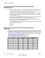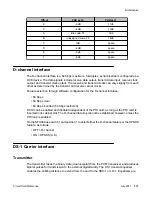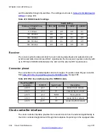
Intersignal Pause:
must accept: > 25 ms
Maximum Dialling Speed:
must accept: 10 signals per second
Noise Rejection: Error Rate in
White Noise
Better than: < 1/2500 calls Test: 10 digit calls nominal
frequency @ -23 dBmO ON/OFF = 50 ms/50ms KP
duration 100 ms SNR = -20 dB all digits
Immunity to Impulse Noise
Better than: < 1/2500 calls Test: 10 digit calls nominal
frequency @ -23 dBmO ON/OFF = 50ms/50ms KP
duration 100 ms SNR = -12 dBs all digits ATT Digit
Simulation Test, Tape #201 from PUB 56201
Error Rate from Power Lines
Better than: < 1/2500 calls Test: 10 digit calls nominal
frequency @ -23 dBmO ON/OFF = 50 ms/50ms KP
duration 100 ms 60 Hz signal @ 81 dBrnc0 (-9dBm)
or 180 Hz signal @ 68 dBrnco (-22dBm) all digits
Tolerate Intermodulation:
Must tolerate @A-B and @B-A modulation products
with a power sum 28 dB below each frequency
component level of the signals.
KP: KP activation
The receiver must not respond to signals prior to KP.
Remain unlocked until ST, STP, ST2P, or ST3P is
received.
Multiple KP's
After the initial KP, subsequent KP's are ignored while
in unlocked mode.
Excessive Components:
If more than two valid frequencies are detected, no
digit is reported to the CPU.
The XMFR receiver specifications conform to the following:
• TR-NPL-000258, Compatibility Information for F.G.D. switched access service, Bell
Communication Research Technical Reference, Issue 1.0, October 1985.
• TR-NPL-000275, Notes on the BOC Intra-LATA Networks, Bell Communication Research
Technical Reference, Chapter 6, 1986.
Physical specifications
The physical specifications required by the NTAG26 XMFR circuit card are shown in the
following table.
Table 208: Physical specifications
Dimensions
Height: 12.5 in. (320 mm) Depth: 10.0 in. (255 mm) Thickness:
7/8 in. (22.25 mm)
Faceplate LED
Lit when the circuit card is disabled
Power requirements
1.1 Amps typical
MF signaling
Circuit Card Reference
July 2011 483
Summary of Contents for 1000 Series
Page 1: ...Circuit Card Reference Nortel Communication Server 1000 7 0 NN43001 311 04 04 July 2011 ...
Page 20: ...20 Circuit Card Reference July 2011 ...
Page 30: ...Introduction 30 Circuit Card Reference July 2011 Comments infodev avaya com ...
Page 116: ...Option settings 116 Circuit Card Reference July 2011 Comments infodev avaya com ...
Page 143: ...Figure 25 CP PIV card front Physical description Circuit Card Reference July 2011 143 ...
Page 148: ...NT4N39AA CP Pentium IV Card 148 Circuit Card Reference July 2011 Comments infodev avaya com ...
Page 287: ...Figure 86 Clock Controller Option 3 Operation Circuit Card Reference July 2011 287 ...
Page 302: ...NT5K21 XMFC MFE card 302 Circuit Card Reference July 2011 Comments infodev avaya com ...
Page 346: ...NT6D80 MSDL card 346 Circuit Card Reference July 2011 Comments infodev avaya com ...
Page 353: ...Figure 96 NTDK16 DLC Functional description Circuit Card Reference July 2011 353 ...
Page 461: ...Figure 147 Paging trunk operation Applications Circuit Card Reference July 2011 461 ...
Page 462: ...NT8D15 E and M Trunk card 462 Circuit Card Reference July 2011 Comments infodev avaya com ...
Page 500: ...NTAK09 1 5 Mb DTI PRI card 500 Circuit Card Reference July 2011 Comments infodev avaya com ...
Page 512: ...NTAK10 2 0 Mb DTI card 512 Circuit Card Reference July 2011 Comments infodev avaya com ...
Page 534: ...NTAK79 2 0 Mb PRI card 534 Circuit Card Reference July 2011 Comments infodev avaya com ...
Page 550: ...NTBK22 MISP card 550 Circuit Card Reference July 2011 Comments infodev avaya com ...
Page 560: ...NTBK50 2 0 Mb PRI card 560 Circuit Card Reference July 2011 Comments infodev avaya com ...
Page 595: ...Figure 165 MGC block diagram Introduction Circuit Card Reference July 2011 595 ...
Page 662: ...NTRB21 DTI PRI DCH TMDI card 662 Circuit Card Reference July 2011 Comments infodev avaya com ...
Page 668: ...NTVQ01xx Media Card 668 Circuit Card Reference July 2011 Comments infodev avaya com ...
Page 700: ......


