


-|Transparent Guide|-
Manual
For proper use of the product, refer to the manuals and be sure to follow the safety
considerations in the manuals.
Download the manuals from the Autonics website.
Installation Order
For details of atLiDAR (PC / mobile) settings, refer to the software manual.
01. Install the laser scanner.
Secure the device to the installation location through three M4 × 0.7 DP 6 mm holes.
02.
Install the laser scanner program to PC.
Download the software provided by Autonics website.
03.
Connect the laser scanner and the PC, and set the network.
Refer to the Network Setting.
04.
Laser scanner function setting
Use atLiDAR (PC / mobile), set each function to adequate the installation environment
of the laser scanner and the obstacles to be detected.
Network Setting
•
Configure the network settings of LiDAR sensor
via atLiDAR (PC).
•
For initial IP address, refer to the table as below.
IP address
192.168.0.1
Subnet mask
255.255.255.0
Gateway
192.168.0.2
Mounting Bracket
① Connect the sensor and the main bracket using 3 M4 × L8 bolts.
② Adjust the beam position using 3 M5 bolts that are fastened to the main bracket.
③ After adjusting the beam position, use 2 M4 × L10 bolts to fix the main bracket so
that it does not shake.
•
For 45 ° / -45 ° / 90 ° installation, additional sub bracket combinations are available.
• For details, refer to the product manual.
① 3 - M4 × L8
③ 2 - M4 × L10
② 3 - M5
[Main bracket]
[Sub bracket]
•
When IP address of the laser scanner and wireless router is same, the communication does
not connected. Set the wireless network (Wifi) to "Disable" in the network settings of the
Windows operating system.
•
This unit may be used in the following environments.
- Indoors / Outdoors (in the environment condition rated in 'Specifications')
- Altitude max. 2,000 m
- Pollution degree 2
- Installation category II
Software
Download the installation file and the manuals from the Autonics website.
Supported devices are different for each software version.
■ atLiDAR (PC, V2.1 or later)
atLiDAR is the management program for laser scanner parameter settings, status
information and monitoring data, etc.
This program communicates with the laser scanner via Ethernet communication.
■ atLiDAR (mobile)
atLiDAR is Android only mobile application that can manage monitoring data such as
laser scanner parameter settings and status information.
Connect the laser scanner with atLiDAR by connecting the USB3.0-C to Ethernet adapter.
Sold Separately
•
Main bracket: BK-LSE2
•
Sub bracket: BK-LSE2-SUB
Product Components
•
Product
•
Instruction manual
Cautions for Installation
• To prevent mutual interference when installing multiple devices, refer to the below.
≥ 6 °
Detection plane
Tilt the devices and install them so that the
scanning planes are tilted to each other.
Screen
Install a screen to block direct laser beam
interference between the devices.
Circuit
■ Photocoupler input
■ PhotoMOS relay output
INPUT
GND
CIRC
UIT
CIRC
UIT
LOAD
Control Input / Output Status
Output
Input
OUT1 (obstacle detection output) OUT2 (error status output)
ON
ON
-
ON
-
OFF
ON
•
Obstacle detection
•
Teaching
•
Error status
•
Scanning ready
(Approx. 10 sec after power
on)
ON
•
Error status
•
Scanning ready
(Approx. 10 sec after power
on)
OFF
•
Obstacle non-detection
OFF
•
Normal status
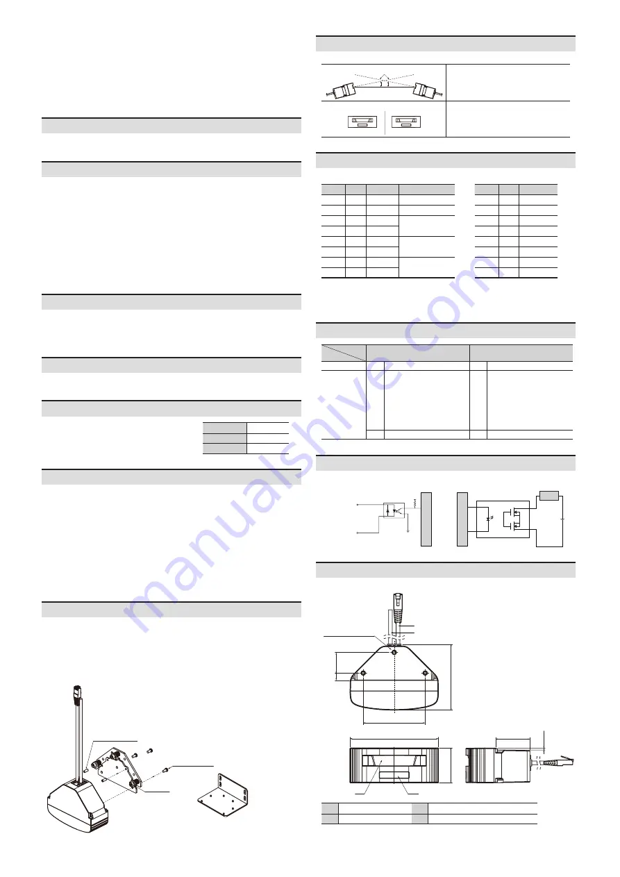
Dimensions
•
Unit: mm, For the detailed drawings, follow the Autonics website.
A
B
C
D
28
3 - M4 ×0.7 DP6.0
84
120
46.5
9.8
89.4
47.5
2.35
A
Ethernet cable
C
Window of laser for detection
B
Power I / O cable
D
Indicators (1, 2), laser for installation
Connections
■ Power I / O cable
Color
Pin
Signal
Function
Brown 1
+V
+V
Blue
2
GND
GND
Yellow 3
OUT1_A
Obstacle detection
output
Green 4
OUT1_B
Red
5
OUT2_A
Error status output
Gray
6
OUT2_B
White 7
IN_A
Output test mode
Black 8
IN_B
■
Ethernet cable
Color
Pin
Signal
White 1
TX+
Black
2
TX-
Red
3
RX+
-
4
-
-
5
-
Green
6
RX-
-
7
-
-
8
-
•
The input / output signals can operate in both direction regardless of the polarity.
•
When the output test mode is not used, do not wire both end of input terminal, or
supply power under 3 VDCᜡ.


