Automationdirect.com Stride SIOL-EI8B User Manual Download Page 74

SIOL-EI8B-USER-M

65

Operation

Powered by

Version 1, May 2022

9.3.2.  Writing an IO-Link device index

Write ISDU Request

Writing an IO-Link device index


To write to the index of a connected IO-Link device, use the EtherNet/IP service Write_ISDU 76 (0x4C).


Send the service to the correct attribute of the IO-Link device parameter object (class code 0x83).


An attribute represents the IO-Link port to which the IO-Link device is connected.

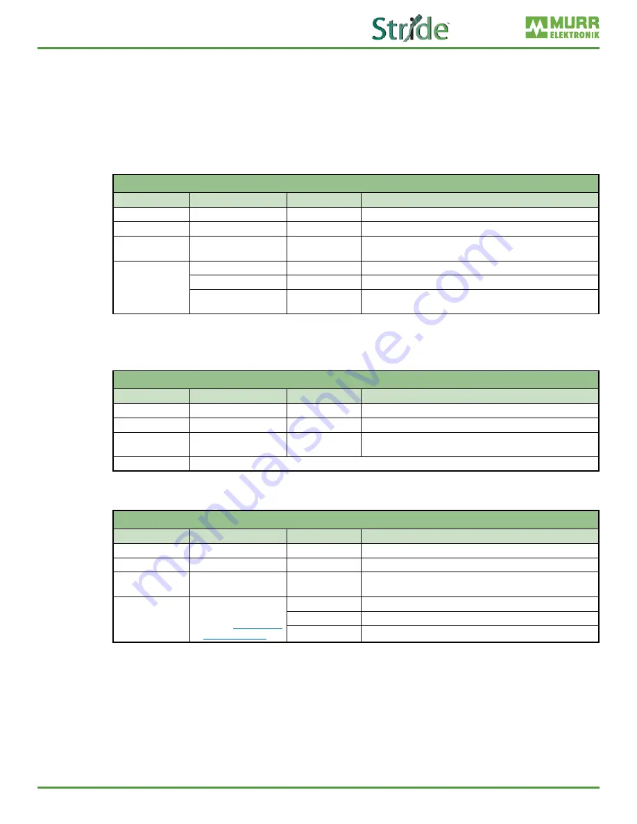
Structure of a write ISDU service request

Structure Of A Write ISDU Service Request

Name

Value

Type

Description

CIP Service

76 (0x4C)

-

ISDU write service

CIP Class

131 (0x83)

-

IO-Link Device Parameter Object

CIP Instance

1 ... Number of 

available IO-Link Ports

-

Addresses the IO-Link Port to which the IO-Link device is connected.

CIP Data

Index

UINT

IO-Link ISDU object index

Subindex

USINT

IO-Link ISDU object subindex

Data

ARRAY of BYTE Data that shall be written to IO-Link device.  

Maximum number of bytes: 232

Write ISDU Response

Positive Response (CIP Status in service response == 0)

The positive response to this service does not hold any CIP data.

Positive Response (CIP Status In Service Response == 0)

Name

Value

Type

Description

CIP Service

76 (0x4C)

-

ISDU write service

CIP Class

131 (0x83)

-

IO-Link Device Parameter Object

CIP Instance

1 ... Number of 

available IO-Link Ports

-

Addresses the IO-Link Port to which the IO-Link device is connected.

CIP Data

The positive response to this service does not hold any CIP Data (Number of bytes: 0).

Negative Response (CIP Status in service response != 0)

Negative Response (CIP Status In Service Response != 0)

Name

Value

Type

Description

CIP Service

76 (0x4C)

-

ISDU read service

CIP Class

131 (0x83)

-

IO-Link Device Parameter Object

CIP Instance

1 ... Number of 

available IO-Link Ports

-

Addresses the IO-Link Port to which the IO-Link device is connected.

CIP Data

The structure of the 

error codes can be 

found in Section 9.3.3, 

“CIP status codes”

UINT

IO-Link Master Error

USINT

IO-Link Device Error

USINT

IO-Link Device Additional Error Code

Summary of Contents for Stride SIOL-EI8B

Page 1: ...Powered by SIOL EI8B IO Link Master Basic EtherNet IP DIO8 IOL8 M12L 5P User Manual SIOL EI8B USER M...

Page 2: ...ent in hazardous environments requiring fail safe performance such as in the operation of nuclear facilities aircraft navigation or communication systems air traffic control direct life support machin...

Page 3: ...e soporte de vida o sistemas de armamentos en las cuales la falla del producto puede resultar directamente en muerte heridas personales o da os f sicos o ambientales severos Actividades de Alto Riesgo...

Page 4: ...n cessitant une s curit absolue par exemple l exploitation d installations nucl aires les syst mes de navigation a rienne ou de communication le contr le de la circulation a rienne les quipements de s...

Page 5: ...ber and the Manual Issue both shown below when communicating with Technical Support regarding this publication Manual Number SIOL EI8B USER M Issue 1st Edition Issue Date 05 2022 Publication History I...

Page 6: ...Code 5 3 1 2 Module structure 6 3 1 3 Connections 7 3 1 3 1 Pin assignments 7 3 1 4 Display elements 8 3 1 5 Rotary switch settings 9 3 2 IO Link 10 3 2 1 Data storage 11 3 3 EtherNet IP 12 3 3 1 Com...

Page 7: ...onfiguration 49 8 2 RPI configuration 51 8 3 IO Link configuration 52 9 Operation 53 9 1 LED indication 53 9 1 1 LED assignment to channel and pin 53 9 1 2 LED flashing behavior 53 9 1 3 LED indicatio...

Page 8: ...3 FIRMWARE menu 80 10 4 4 FACTORY RESET menu 80 10 5 User Administration 81 10 6 Digital IO Channels IO Overview 81 10 6 1 Input data 81 10 6 2 Output data 82 11 Maintenance and cleaning 84 Appendix A...

Page 9: ...iv B 3 Diagnostic Buffer 95 B 4 Digital Output 95 Appendix C Configuring a Module Using Studio5000 Logix Designer 96 C 1 Loading the EDS files 96 C 2 Adding a module to the network 98 C 3 Module confi...

Page 10: ...Read the documentation carefully before starting up the device Store the manual in a place that is accessible to all users at all times for the entire service life of the device You will need general...

Page 11: ...ion and notes DOCUMENTATION RECOMMENDATION Notes with this symbol are references to additional information elsewhere in the documentation Instructions for use An arrow marks instructions Read and foll...

Page 12: ...to put it into operation They are qualified if they meet the following requirements They have undergone suitable electrical engineering training They were trained by the machine operator to operate th...

Page 13: ...ndustrial environments Radio interference may occur if used in domestic or mixed environments If the fieldbus module is used in domestic or mixed environments the applicable standards must be observed...

Page 14: ...apsulated case Vibration proof Reliable even when subjected to continuous vibration Resistant Long life due to acid and alkali resistant plastic Reliable connections Connections tested up to degree of...

Page 15: ...or IO Link M12 A coded 0 Channel corresponds to pin 4 1 Channel corresponds to pin 2 XD1 Power supply POWER IN M12 L coded 5 pin XD2 Power supply POWER OUT M12 L coded 5 pin 1 Rotary switch Fig 3 1 M...

Page 16: ...ded X0 X7 Pin 1 24VDC Pin 2 DI DO Pin 3 0V Pin 4 DI DO IO Link Pin 5 0V M12 Male Female Connector L coded POWER IN OUT XD1 XD2 Pin 1 24VDC US operating voltage 1 2 3 4 5 Pin 2 0V UA actuator voltage P...

Page 17: ...ital inputs and outputs or IO Link 1 LED MS module configuration status LED NS network status LED LNK1 ACT1 Ethernet port 1 link activity LED ST module overall status LED LNK2 ACT2 Ethernet port 2 lin...

Page 18: ...ess The IP address saved last is used 192 168 1 6 by default 256 776 Reserved 777 Fixed IP The IP address is set STATIC at 192 168 100 177 778 912 Reserved 913 Deactivate web server Disables the web s...

Page 19: ...one or more IO Link devices A master module has one or more ports and one device can be connected to each port IO Link is a point to point communication system and is not a fieldbus The IO Link master...

Page 20: ...Restore data storage for an IO Link device on a given IO Link port the port must be setup as follows see Section 7 4 4 for IO Link port parameter details Parameter IO Link Port X_ IO Link Function Pi...

Page 21: ...times as each user must evaluate messages that are not addressed to the user Excessive network traffic may result in missed messages and RPI response delays which may interrupt communication It is the...

Page 22: ...I time by a factor of 4 Please note a Configurations which require RPI times shorter than 10ms must be tested in advance for correct operation b The minimum supported RPI time is 1 ms For further info...

Page 23: ...M12 4 pin D coded IO Link IO Link devices operating voltage 24VDC IO Link devices voltage range 20 30V Transfer rate 4 8 38 4 or 230 4 kbit s COM1 COM2 COM3 Standardized Master Interface SMI IO Link V...

Page 24: ...1 2 Type 1 Type 3 Short circuit protection sensor supply MOSFET with current measurement Connector M12 5 pin A coded Conductor cross section 18 AWG Conductor length 30m 98ft Total current Per port 2A...

Page 25: ...l Data Powered by Version 1 May 2022 Derating Charts Fig 4 1 Sensor current US and actuator current UA Fig 4 2 Total current sensor power supplies Total current outputs Fig 4 3 Derating Current per se...

Page 26: ...enclosure EN 55016 2 3 EMC Inteference Protection degree EN 60529 IP67 Protection class Using a SELV or PELV power supply III Pollution degree 2 EMC Immunity Electrostatic discharge ESD EN 61000 4 2 E...

Page 27: ...1 3rd Ed CSA C22 2 NO 61010 2 201 18 2nd Ed E201820 ULus UL 61010 1 3rd Ed UL 61010 2 201 2nd Ed E201820 China RoHS GB T 26572 25 EPUP Hazardous Substances 25 Part Name Lead Pb Mercury Hg Cadmium Cd H...

Page 28: ...ion Provide suitable grounding Select a suitable installation site in terms of vibration and shock load temperature and humidity see Section 4 Technical Data Protect connections to avoid stress to con...

Page 29: ...OTE For correct installation and improved heat dissipation we recommend keeping a minimum distance of 3mm 0 12 in when mounting the STRIDE IO Link master NOTE If angled male connectors are used a mini...

Page 30: ...ucture Carefully tighten the screws The indicated tightening torques must be adhered to NOTICE Material damage through improper use Do not use the modules as climbing aids Improper use can cause the m...

Page 31: ...ing to the torque 5 Ground the module Attach the grounding strap as shown in Section 5 4 1 Functional ground NOTE The screws and the grounding strap illustrated are not included with the device 5 4 1...

Page 32: ...SER M 23 Mounting Powered by Version 1 May 2022 5 4 2 Rotary switch cover Screw Size Torque Tool Required M3 0 8 N m 7 in lb Phillips Screwdriver Part TW SD PH 1 Fig 5 5 Rotary switch cover installati...

Page 33: ...e requirements and regulations for safety electro magnetic compatibility and if required telecommunication terminal equipment specifications as well as the specification data CAUTION Hot surface Minor...

Page 34: ...b M12 Torque Wrench The pin assignment of the slots can be found in Section 3 1 3 Connections NOTE Feeding in an external ground via M12 female connectors can lead to faults Do not feed external groun...

Page 35: ...the M12 female connector Supported IO Link communication The module supports the IO Link communication using the following speeds 4 800 baud COM 1 38 400 baud COM 2 230 400 baud COM 3 NOTE The module...

Page 36: ...power supply Connect M12 male connector to POWER IN and M12 female connector to POWER OUT Screw Size Torque Tool Required M12 0 6 N m 5 in lb M12 Torque Wrench The pin assignment of the slots can be f...

Page 37: ...2022 6 2 Ensuring Tightness IP67 CAUTION Not properly sealed Risk of personal injury and material damage due to failure caused by ingress of conductive liquids Unused male and female connectors must b...

Page 38: ...hases e g first start up restart and configuration changes Always perform the start up in this sequence 1 Mount and connect cables to the module 2 System check and approval by an expert 3 Put it into...

Page 39: ...Implicit Below we show how to quickly get started using any EtherNet IP capable Productivity PLC 1 Download the IO Link Master EDS file from AutomationDirect com 2 Open Productivity Suite and start a...

Page 40: ...your download location and double click the EDS file you downloaded for your IO Link Master The EDS file will be added to your EDS library and is now searchable by Description Part Number Device Type...

Page 41: ...e module Code has also been developed for communicating with a variety of IO Link field devices via the IO Link Master module To use the quick start code go to Section 7 3 Quick start IO Link Producti...

Page 42: ...iguration 3 Click the icon to add a new EtherNet IP message A list of available connections will be displayed The appropriate selection will depend on the connected IO Link devices For this example we...

Page 43: ...Specify a data array for both the T O INPUT and O T OUTPUT tabs The required size of each array will depend on the selected Connection from step 3 Specify an integer tag for the Extended Status field...

Page 44: ...rsion 1 May 2022 Fig 7 9 EtherNet IP Device O T Configuration The input and output tags created for T O and O T data can be found in the tag database see the example in Fig 7 10 Fig 7 10 Tag Database...

Page 45: ...2 5 Select the Config Data tab and modify parameters as needed Fig 7 11 EtherNet IP Device Config Data 6 When configured as desired click OK The Hardware Configuration window will now have the new EIP...

Page 46: ...Suite Integration Library AutomationDirect com has created quick start code that can be imported into the task library and used to connect to the module Code has also been developed for communicating...

Page 47: ...022 Fig 7 13 Task Library Import Group 4 Navigate to your download location select the Stride Murr IO Link_Masters adtkl file you downloaded for your IO Link Master and click Import The Stride Murr IO...

Page 48: ...15 Task Library IO Link Master Group 5 Drag the new task from the Task Library into the Run Every Scan task folder and click OK on the Tag Conversion pop up The new task and associated tags have now...

Page 49: ...cture that was created as part of step 5 b For the Device Name type IO Link Master the name must be exact to work with the quick start code c Enter the appropriate IP Address d Click the icon and sele...

Page 50: ...SIOL EI8B USER M 41 Startup Powered by Version 1 May 2022 Fig 7 17 EtherNet IP Client Properties IO Link Master...

Page 51: ...ta Array 8 Once all required field and tag entries have been made per step 7 click OK and the EtherNet IP Device will now appear in the hardware field You are now ready to setup the quick start code f...

Page 52: ...Copy Data Call Task and Copy Data instructions as shown on rung 1 in Fig 7 21 The IO Link port number that the Murr MVP IO Link Hub is connected to on the master module must correspond to the index n...

Page 53: ...gth Instance Length E01 Digital IOs IOL 32 bytes with status and diagnostics 101 394 111 260 Input Only connection Input Only Connection Configuration assembly Description Input assembly Output assemb...

Page 54: ...161 IO Link port X3 input status 162 169 IO Link port X4 input data 170 201 IO Link port X4 input status 202 209 IO Link port X5 input data 210 241 IO Link port X5 input status 242 249 IO Link port X...

Page 55: ...eport 1 Undervoltage UA diagnostic report 5 6 Reserved Fixed 17500 Do not modify value 7 No Actuator Supply Diagnostic Message 0 Do Not Report 1 Report 1 Diagnostic report no UA 8 LED Indication For S...

Page 56: ...al Input Signal Filter Pin 4 0 No Filter 1 1 ms 2 3 ms 3 5 ms 4 10 ms 5 15 ms 0 Digital input signal filter pin 4 13 Digital Input Signal Filter Pin 2 0 Digital input signal filter pin 2 14 15 Reserve...

Page 57: ...rtup Powered by Version 1 May 2022 WebUI parameters WebUI Parameters Byte Parameters Value Default value Description 0 Use Of WebUI 0 Disabled 1 Enabled 1 Activates or disables the WebUI 1 Reserved 0...

Page 58: ...n import the EDS files into your programming software see Section 7 1 Loading the EDS files for an example of how to do this Using the EDS file allows you to benefit from the advantages of a preconfig...

Page 59: ...ers must be transferred to the CPU NOTE Configuration parameters are only transferred to the module during the Forward Open process and com munication between the CPU and the module is briefly interru...

Page 60: ...n Powered by Version 1 May 2022 8 2 RPI configuration Setting the RPI values The RPI value is set in the EtherNet IP Device properties which is found in the EtherNet IP tab of the Hardware Config Fig...

Page 61: ...n EtherNet IP IO Link Device Tool IO Link device configuration through EtherNet IP Explicit Messages It is possible to configure the connected IO Link devices through EtherNet IP Explicit Messages For...

Page 62: ...ndication for bus LED indication POWER Extended LED indications The LEDs on the front panel of the module are labeled for clear identification of the displayed information 9 1 1 LED assignment to chan...

Page 63: ...ircuit at pin 2 Red Flashing at 1Hz Overload short circuit in sensor supply 24V Pin1 Off Off Pin 2 is not used or deactivated Error at Input or Output If an error occurs at an input or output the asso...

Page 64: ...tion Condition Description Green Steady on Module in operation Green Flashing at 1 Hz Standby The module has not been configured Green Red Flashing at 1 Hz Self test Red Flashing at 1 Hz Major recover...

Page 65: ...sending receiving Ethernet frames Off Off The module is not sending receiving Ethernet frames 9 1 6 LED indication for State LED Indication Overview ST indicates the state of the overall module LED In...

Page 66: ...ation Condition Description Green Steady on 18V US 30V Error free operation Red Steady on 11V US 18V Undervoltage Red Flashing at 4 Hz US 30V Overvoltage Off Off US 11V No voltage NOTE At US 18V an er...

Page 67: ...e Module LED Indication Condition Description MS NS ST POWER UA POWER US Green Flashing at 1 Hz Identification of the module Extended LED display factory reset Extended LED Display Factory Reset LED I...

Page 68: ...rt circuit diagnostic Global Error Code 0x01 table 5 ErrorCode Byte2 For IO Link this is the MSB of the IO Link ErrorCode otherwise it is the Specific Error Code see the Short circuit diagnostic Globa...

Page 69: ...Voltage External Actuator Power Supply 0x2B Undervoltage Sensor Power Supply 0x32 No Voltage Sensor Power Supply 0x33 Undervoltage U1 0xD0 Undervoltage U2 0xD1 9 2 3 3 Overvoltage diagnostic Overvolt...

Page 70: ...or 0x980B Backup Inconsistency Upload Fault 0x980C Parameter Inconsistency Download Fault 0x980D Port Class B Failure Power Missing 0x980E Short Circuit At Pin 2 0x980F Revision Fault 0x9811 Compatibi...

Page 71: ...vice Supply Voltage Under Run U4 0x5114 Device Supply Voltage Under Run U5 0x5115 Device Supply Voltage Under Run U6 0x5116 Device Supply Voltage Under Run U7 0x5117 Device Supply Voltage Under Run U8...

Page 72: ...te Device 5 0x7705 Wire Break Of Subordinate Device 6 0x7706 Wire Break Of Subordinate Device 7 0x7707 Wire Break Of Subordinate Device 8 0x7708 Wire Break Of Subordinate Device 9 0x7709 Wire Break Of...

Page 73: ...Value Type Description CIP Service 75 0x4B ISDU read service CIP Class 131 0x83 IO Link Device Parameter Object CIP Instance 1 Number of available IO Link Ports Addresses the IO Link Port to which the...

Page 74: ...to IO Link device Maximum number of bytes 232 Write ISDU Response Positive Response CIP Status in service response 0 The positive response to this service does not hold any CIP data Positive Response...

Page 75: ...on unknown Addressed CIP Class or CIP Instance is not known 8 0x08 Service not supported The requested service is not implemented or was not defined for this Object Class Instance 19 0x13 Not enough d...

Page 76: ...1 May 2022 10 Web Server WebUI The Murrelektronik web server WebUI is a graphic tool that you can use to obtain information about the device quickly and intuitively Fig 10 1 The Murrelectronik WebUI...

Page 77: ...he IP address of the device in the web browser The WebUI startup screen is the Status page Operating areas The WebUI is divided into 4 operating areas Fig 10 2 Operating areas 1 System tree Shows the...

Page 78: ...ne of the system tree the device is displayed with part number and product name The menu bar comprises the following clickable menu items Status Parameters Diagnostics Maintenance Fig 10 3 Menu bar 10...

Page 79: ...n in the device Webpage version Currently running version of the web server WebUI in the device Maintenance information NOTE The maintenance information here is read only Any entry or changes to the f...

Page 80: ...the master The menu shows an overview of diagnostic messages Depending on the setting in the Please select an entry drop down menu the following diagnostics of the module are displayed Active All diag...

Page 81: ...r WebUI Powered by Version 1 May 2022 Fig 10 6 Menu item Diagnostics 10 2 4 MAINTENANCE menu In the Maintenance menu item users with admin and operator rights can erase the diagnostic memory Fig 10 7...

Page 82: ...ndividually Depending on the user role information can be read or functions can be configured here When IO Link communication is active the IO Link device name automatically appears under the relevant...

Page 83: ...Status Digital output Port Status pin 1 Port Status pin 1 displays the following information Port Status Pin 1 Parameter designation Meaning Temperature C Temperature in degrees Celsius Voltage V Volt...

Page 84: ...g information IO Link Device Information Parameter designation Meaning Min cycle time Minimum process cycle time of the IO Link device Function ID Function ID of the IO Link device Number of profile I...

Page 85: ...uration values Fig 10 12 IO Link master port configuration pin 4 10 3 4 IO LINK PARAMETER menu In this menu item the ISDU Index Service Data Unit of the device can be read during IO Link operation Thi...

Page 86: ...ontinuously displayed if pin 4 of the corresponding port has been configured as an IOL port Example port X2 pin 4 IO Link autostart and pin 2 digital output statically on Fig 10 14 IO Link master port...

Page 87: ...TE Factory default IP address setting for the module is DHCP The Settings Maintenance Device Configuration menu allows users to configure a static IP address subnet mask and gateway Fig 10 16 IP addre...

Page 88: ...ATION menu Users with service maintenance and admin rights can enter the device information here Fig 10 17 Setting maintenance information The maintenance information appears in the device under the m...

Page 89: ...nd admin rights can upload new firmware provided in ZIP folders to the device After a successful upload the device checks the firmware container and automatically starts with the new firmware version...

Page 90: ...ged from the controller in the plant with the fieldbus running Users log in and out at the bottom left of the system tree Fig 10 21 User management 10 6 Digital IO Channels IO Overview In the Configur...

Page 91: ...forcing outputs Users with admin service and maintenance rights can allow enable forcing of outputs in this menu The right to do this is only granted if the module is not in an active fieldbus connec...

Page 92: ...outputs All other users admin operator maintenance are allowed to force outputs As soon as the user admin operator maintenance logs out the outputs default to 0 As soon as a fieldbus is actively work...

Page 93: ...nce and cleaning NOTICE Damage caused by defective or damaged devices The functioning of the modules is not guaranteed Replace defective or damaged devices Device cleaning Use only oil free compressed...

Page 94: ...ned to this attribute is one 01 6 Get Max ID Class Attribute UINT The attribute ID number of the last class attribute of the class definition implemented in the device The value of this attribute will...

Page 95: ...t Class Code 0x04 Class Attribute Assembly Object Class Attribute Attribute ID Access Rule Name Data Type Attribute Description Semantics of Value 1 Get Revision UINT Revision of this object The curre...

Page 96: ...vice Code Implemented for Service Name Service Description Class Instance 0x0E Yes No Get_Attribute_Single Returns the contents of the specified attribute A 1 5 Device Level Ring DLR Object Class Code...

Page 97: ...ed object at this class hierarchy level This attribute will show one 01 Instance Attribute Quality of Service Object Instance Attribute Attribute ID Access Rule Name Data Type Attribute Description 1...

Page 98: ...tifying the physical link object 5 Set Get Interface Configuration STRUCT of TCP IP network interface configuration IP Address UDINT The device s IP address Network Mask UDINT The device s network mas...

Page 99: ...is four 04 If updates that require an increase in this value are made then the value of this attribute increases by 1 2 Get Max Instance UINT Maximum instance number of an object currently created in...

Page 100: ...ransmitted frames which experienced exactly one collision Multiple Collisions UDINT Successfully transmitted frames which experienced more than one collision SQE Test Errors UDINT Number of times SQE...

Page 101: ...ar sevice is only implemented for the attributes 4 and 5 A 2 Vendor Specific Objects A 2 1 IO Link Device Parameter Object Class Code 0x83 Class Attribute IO Link Device Parameter Object Class Attribu...

Page 102: ...4B No Yes Read_ISDU Read the parameter in the IO Link Device in raw format i e Big Endian 0x4C No Yes Write_ISDU Write the parameter in the IO Link Device in raw format i e Big Endian Read_ISDU Servic...

Page 103: ...1 0 7 6 5 4 3 2 1 0 Port X7 X6 X5 X4 X3 X2 X1 X0 X7 X6 X5 X4 X3 X2 X1 X0 Pin 2 2 2 2 2 2 2 2 4 4 4 4 4 4 4 4 Channel 17 16 15 14 13 12 11 10 07 06 05 04 03 02 01 00 NOTE The tables for Port and Pin B...

Page 104: ...set when valid process data is exchanged between master and device It is reset if the process data is not valid 2 3 Vendor ID of connected IO Link device 4 7 Device ID of connected IO Link device B 3...

Page 105: ...5000 Logix Designer Appendix C Configuring a Module Using Studio5000 Logix Designer from Rockwell Automation C 1 Loading the EDS files Installing the EDS files and or the module description file Fig C...

Page 106: ...Logix Designer Fig C 2 EDS Wizard Click Next and follow the instructions of the dialog window Finish the installation of the EDS files The modules can now be selected and added to the network NOTE Th...

Page 107: ...Adding a module to the network Adding new modules Fig C 3 New Module In the Controller Organizer Ethernet Click New Module In the following dialog window modules are shown which a have been registered...

Page 108: ...ered by Version 1 May 2022 Configuring a Module Using Studio5000 Logix Designer Alternative module selection The dialog window can also be called via the menu Files New Component Module Fig C 4 Altern...

Page 109: ...Searching a module Use the input mask to search for the module that you want to add to the network a Use search terms which describe the desired module e g product number product name or manufacturer...

Page 110: ...odule Using Studio5000 Logix Designer General settings Fig C 6 General settings In New Module General Assign a unique module name Assign the IP address In New Module Connection Assign further settings...

Page 111: ...connection or b call the settings again by double clicking the module Fig C 7 Module Definition In Module Definition Click Change A new window appears Set the number or the type of connection here Se...

Page 112: ...the EDS in the programming software and the selection of a connection suitable for the application the configuration files can be found in the controller tags The input and output tags associated with...

Page 113: ...the RPI values Searching the module When setting up an EtherNet IP system the RPI value must be carefully set in the controller To set the RPI values the module properties must be selected In Controll...

Page 114: ...ay 2022 Configuring a Module Using Studio5000 Logix Designer Setting the RPI values Fig C 10 Setting the RPI values Click the Connection tab Set the desired RPI values in the column Requested Packet I...

Page 115: ...perior layer If they do not match the frame is discarded EtherNet IP Ethernet Industrial Protocol Open standard for industrial networks that supports both cyclic and acyclic transfer of messages and u...

Page 116: ...o use this technical documentation to create their own technical documentation For this purpose the documentation produced by Murrelektronik GmbH may be changed in parts or amended or copied and trans...

Page 117: ...Powered by Although the information in this manual has been compiled with utmost care we are not responsible for the completeness and relevance of the information 770 844 4200...

Reviews: