background image


Page 9 of 26 

7/9/19

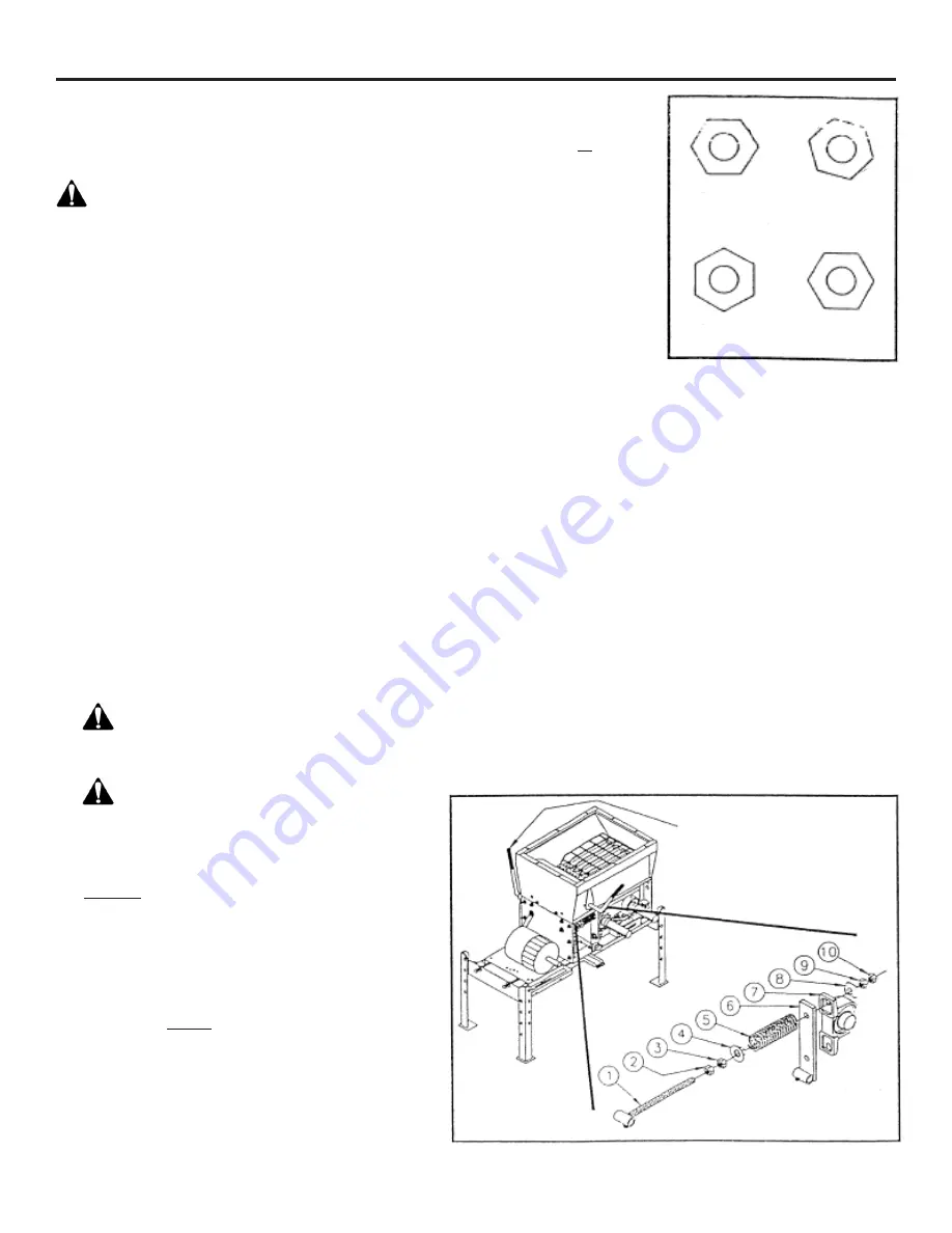
6  Once the roll teeth 
 

touch, turn the 


nuts (9) IN about 


1/4 to 1/2 flat on 


the nut. (See 


Figure 7).


NOTE: There are 


six flat sides on 


each nut. Turning 


one full flat means 


turning the nut so 


that the flats 


advance one 

 position.

7  Hold the nuts (9) in 
 

place and tighten the jam nuts (10) on both sides of 


the mill. Recheck that the rolls do not touch by 


repeating step 5.

8  Move the roll spacing adjustment handle 50 each way 
 

from center and check to assure the rolls are not 


touching. Readjust if necessary. Be sure to tighten jam 


nuts (10) when finished.

9  If adjustments were made, measure the length of the 
 

springs (5). They should be 4 1/2” long ±1/8”. If 


spring adjustment is needed, loosen the jam nut 


(2) on the spring side and move spring nut (3) until 


the correct spring length is established. Once 


adjusted, tighten the jam nut (2) to hold setting.

10  Make a final check of the rolls for parallel and roll 
 

gap. You may need to use a feeler gauge for 8 cut and 


finer rolls. Reinstall the drive belt and shields. Be sure 


to remove any tools from the machine before  

 restarting.

Figure 7

Figure 8

REALIGNING ROLLS

REALIGNING ROLLS - If the rolls ever become out of
alignment (more gap on one end of the roll pair than 
the other) they must be realigned to maintain feed 
consistency and prolong the life of the rolls. To accomplish 
this, follow the instructions below.


  DANGER: Before attempting to service your 

roller mill be sure to follow the SAFETY SHUTDOWN 
PROCEDURE on page 2.

Remove the drive belt from all the pulleys and lay it 


aside. Loosen the jam nut (item 10) on one of the 


sides of the mill. It may be necessary to loosen and 


adjust both sides to acquire the correct settings. This 


will be determined by how far out of parallel the rolls 

 are.

2  Adjust the other nut (9) on the same side, until the 
 

rolls are parallel. To check for roll spacing, a strip 


of metal banding works well but any strip of metal 


approximately 1/32” thick will also work. Slide the 


strip between the rolls and verify the roll spacing is 


the same along their entire length. Check the spacing 


3 or 4 times with the rolls at various rotated positions 


to assure the rolls are as close to parallel as possible. 


NOTE: Rolls will vary a few thousandths of an inch  


in diameter along their length, be sure to check for  


the tightest gap.

3  With the rolls parallel you can now set the roll 
 

spacing. Place the roll spacing adjustment handle 


straight up with the indicator straight down. This will 


place the rolls at their closest possible setting.

4   

 WARNING: Be careful not to get your hands 


between the rolls or between the rolls and the basic 

 channel.


 WARNING: Do not power the mill with the 


motor. This creates a personal danger to you and 


may cause damage to the rolls if they are touching.

5  By hand, spin the rolls in the same direction 
 

(clockwise) at different speeds. Strike the idler roll 


shaft at the bearing, towards the drive roll, with a 


rubber mallet to ensure that the idler bearing 


mount (6) is free to allow the rolls to be at their 


closest position. With the rolls spinning freely at 


different speeds, turn the nuts (9) on both sides of 


the mill out evenly until you hear the roll teeth 


touch. They will make a ticking sound that should 


be easily heard. This is to ensure that the rolls do 


not move closer together with the vibration of the 


mill. Some additional adjustment may be needed 


at this time.

292-1329  5/94

ROLL SPACING

ADJUSTMENT

ORIGINAL

1/2 FLAT

1/4 FLAT

1 FLAT

1

1

1

1

2

2

2

2

3

3

3

3

4

4

4

4

5

5

5

5

Summary of Contents for LPE 500

Page 1: ...Page 1 of 26 7 9 19 LPE 500 LPE 700 LOW PROFILE ELECTRIC STATIONARY ROLLER MILL Operator Parts Installation Manual ...

Page 2: ...mation now for future reference and convenience Always give this information to your dealer when ordering new parts If at any time it becomes necessary for you to write directly to Automatic Equipment Manufacturing Company for additional information give the model and serial number of your machine and as much descriptive information as possible It will enable us to more thoroughly and quickly expe...

Page 3: ...son be permitted to operate this mill without a thorough understanding of how the machine works and the precautions to be observed If the mill discharges into an auger be sure the auger is covered and shields are provided between the mill discharge and the auger Because of the dry highly flammable material associated with this machine FIRE FIGHTING EQUIPMENT SHOULD BE READILY AVAILABLE DURING THE ...

Page 4: ...the skin and may also infect a minor cut or opening in the skin If injured by escaping fluid see a doctor at once Make sure all connections are tight and that hoses are in good condition SAFETY PRECAUTIONS SERVICE AND REPAIR 1 SAFETY SHUTDOWN PROCEDURE Working on the mill when it is operating is expressly prohibited Never clean adjust lubricate or otherwise service this machine until the following...

Page 5: ... power DON T OVERCROWD ROLLS Keep a ribbon of grain feeding between the rolls and you ll do a more consistent job of rolling This is especially true of oats and barley It is not necessary to completely flatten the kernel of any grain being rolled Grain is easier to digest when the hard coat or hull is broken open or cracked exposing their nutrients to the digestive juices of livestock ROLL SPACING...

Page 6: ...ld always be followed to ensure that the rolls are free from excess grain build up that may prevent the mill from starting up properly 1 When shutting down your mill always stop the flow of grain into the hopper first 2 When all grain has passed through the rolls and the hopper is empty the hopper gate control should be closed rotated clockwise 3 Finally disengage the electrical power to the rolle...

Page 7: ...GS All pillow block bearings are sealed and as a general rule REQUIRE NO LUBRICATION However the bearing manufacturer does furnish grease zerks and recommends that the bearings be greased before 1 3 of the bearing s calculated life elapses Usually a pump or two of grease every 100 hours of operation will be sufficient IMPORTANT DO NOT OVERGREASE Overgreasing can cause damage to the bearing seal Ea...

Page 8: ...s part of the general maintenance of your roller mill Like any other implement your roller mill requires proper care and intelligence in operation Misuse and or neglect will only cause unnecessary expense and dissatisfaction WARNING SHIELDS AND GUARDS ARE PROVIDED FOR YOUR PROTECTION Although some shields and guards may need to be removed or opened for servicing and adjustments they should always ...

Page 9: ...ides to acquire the correct settings This will be determined by how far out of parallel the rolls are 2 Adjust the other nut 9 on the same side until the rolls are parallel To check for roll spacing a strip of metal banding works well but any strip of metal approximately 1 32 thick will also work Slide the strip between the rolls and verify the roll spacing is the same along their entire length Ch...

Page 10: ...Bearing Mount When you order in this way you can be certain the correct part will be delivered in the shortest time possible IMPORTANT Use only genuine factory replacement parts on your roller mill Do not substitute homemade or non typical parts If a bolt is lost or in need of replacement for your safety and the preservation of your roller mill be sure to use a replacement bolt of the same grade U...

Page 11: ...ING Q1 1 3 4 BROWNING 1 13 205 0292 SHEAVE 4TB48 BROWNING 1 14 205 0307 SHEAVE 4TB62 BROWNING 2 DRIVE ASSEMBLY Item No Part No Description Qty 1 100 0224 3 8 x 3 8 x 2 Key 2 2 100 0304 5 16 x 5 16 x 2 3 4 Key 1 3 201 0120 5 16 18 x 1 Hex Head Bolt Grade 5 ZP 6 4 201 0368 3 8 16 x 1 1 4 Hex Head Bolt Grade 5 ZP 3 5 201 0469 5 16 18 x 1 Hex Head Bolt Grade 5 ZP 3 6 201 1107 5 8 11 x 9 Hex Head Bolt ...

Page 12: ...Page 12 of 26 7 9 19 BASIC 1 3 11 13 7 10 2 4 8 14 22 35 40 3 30 16 15 21 20 32 33 11 36 39 41 43 38 34 5 6 LPE500 700 BASIC ASSEMBLY 18 26 23 24 27 29 35 37 42 12 17 9 28 19 31 14 25 ...

Page 13: ...9 LPE700 Drive Roll Side End Plate 1 17 102 4003 Cam Adjustment Pivot LPE 2 18 102 4006 Flat Bearing Stop Bolt On LPE 2 19 150 0028 LPE500 Rubber Baffles 2 150 0037 LPE700 Rubber Baffles 2 20 201 0024 1 2 13 x 1 Carriage Bolt Grade 5 4 21 201 0034 3 8 16 x 1 Carriage Bolt Grade 5 ZP 14 22 201 0081 3 8 16 x 3 4 Hex Head Bolt Grade 2 ZP 2 23 201 0111 1 4 20 x 3 4 Slot Truss Head Screw 6 24 201 0346 ...

Page 14: ...Page 14 of 26 7 9 19 HOPPER ASSEMBLY LPE500 700 HOPPER ASSEMBLY 5 6 1 4 2 3 7 10 8 9 11 13 12 14 15 16 ...

Page 15: ...PE700 Hopper 1 6 61 3956 LPE500 Gate Slope 1 61 4003 LPE700 Gate Slope 1 7 102 3996 Bolted Link Arm 2 8 201 0050 1 4 20 x 3 4 Hex Head Bolt Grade 5 ZP 4 9 201 0193 1 4 20 x 1 2 Hex Head Bolt Grade 5 ZP 4 10 201 0443 3 8 16 x 1 Hex Head Bolt Grade 5 ZP 4 11 201 0448 1 4 20 x 1 1 2 Hex Head Bolt Grade 5 ZP 1 12 202 0090 3 8 16 Hex Nylon Insert Lock Nut ZP 4 13 202 0102 1 4 20 Hex Nylon Nut ZP 5 14 2...

Page 16: ...Page 16 of 26 7 9 19 PRIMARY ASSEMBLY 1 2 3 5 6 7 8 9 10 11 13 14 15 16 17 18 20 22 23 24 25 26 31 32 28 27 29 30 33 4 12 21 19 ...

Page 17: ...ly 1 9 100 0544 3 16 x 3 16 x 1 Key 1 10 101 3323 Idler Support Third Rod Washer 1 11 200 1419 3 4 Hole Plug 1 12 201 0008 3 8 16 x 1 1 4 Carriage Bolt Grade 5 8 13 201 0024 1 2 13 x 1 Carriage Bolt Grade 5 4 14 201 0120 5 16 18 x 1 Hex Head Bolt Grade 5 ZP 8 15 201 0193 1 4 20 x 1 2 Hex Head Bolt Grade 5 ZP 6 16 201 0368 3 8 16 x 1 1 4 Hex Head Bolt Grade 5 2 17 201 0377 1 2 13 x 5 1 2 Hex Head G...

Page 18: ...ZP 9 11 203 0009 5 16 LOCK WASHER 8 BELT DRIVE SHIELDS Item No Part No Description Qty 1 61 3977 Shroud 1 2 100 0899 Shield Tether Cable 1 3 101 2532 Belt Shield Filler 1 4 101 4986 Motor Hole Shield 1 5 101 5011 Drive Pulleys Shield 1 6 201 0112 1 4 20 x 1 2 Slot Truss Head Screw 2 7 201 0120 5 16 18 x 1 Hex Head Bolt Grade 5 ZP 9 8 202 0069 1 4 20 Hex Flange Whiz Lock Nut ZP 2 9 202 0070 5 16 18...

Page 19: ...00 0545 1 4 X 1 4 x 2 Key 1 6 101 2306 Clean Out Door Cover 2 7 101 5010 Auger Base Leg Clamp 2 8 201 0007 3 8 16 x 1 Hex Head Bolt Grade 2 ZP 8 9 201 0120 5 16 18 x 1 Hex Head Bolt Grade 5 ZP 6 10 201 0351 5 8 11 x 2 Hex Head Bolt Grade 5 ZP 1 11 202 0070 5 16 18 Hex Flange Whiz Lock Nut ZP 10 12 202 0073 5 8 11 Whiz Flange Lock Nut ZP 1 13 203 0003 3 8 Flat Washer ZP 8 14 203 0006 5 8 Flat Washe...

Page 20: ...Page 20 of 26 7 9 19 DISCHARGE AUGER Option LPE500 700 DISCHARGE AUGER OPTIONAL 1 2 3 4 5 7 8 9 10 11 13 14 15 12 16 17 18 19 20 21 22 25 26 23 24 6 ...

Page 21: ...w Adapter 1 10 201 0067 5 16 18 x 5 16 Socket Head Cap Knurled S S 1 11 201 0119 5 16 18 x 3 4 Carriage Bolt Grade 5 ZP 3 12 202 0002 5 16 18 Hex Nut ZP 10 13 202 0070 5 16 18 Hex Flange Whiz Lock Nut ZP 3 14 203 0002 5 16 Flat Washer ZP 4 15 203 0009 5 16 Lock Washer 4 16 207 0478 Auger Exit Shaft End Cap 1 17 209 0032 1 Flangette Bearing Insert 1 18 211 0023 1 Flangette Housing 2 19 221 0001 1 L...

Page 22: ...ve as necessary 4 POSSIBLE CAUSE Gravel in the grain SUGGESTED REMEDY Sand and small gravel is difficult to remove from grain because of similar sizes as grain Larger gravel and small rocks can be removed by screening with wire hardware cloth on a frame mounted in the hopper PROBLEM MILL IS HARD TO START 1 POSSIBLE CAUSE Grain between rolls SUGGESTED REMEDY Close hopper gate and separate rolls to ...

Page 23: ...efer to factory recommendations regarding spring tension See page 8 5 POSSIBLE CAUSE Rolls out of alignment SUGGESTED REMEDY Realign rolls See page 8 6 POSSIBLE CAUSE Baffles between rolls and hopper have too much clearance SUGGESTED REMEDY Remove hopper and adjust baffle by bending material so clearance is less than 1 8 inch Rubber baffles will sing for a while but will quiet down after a few min...

Page 24: ...lls for different varieties of grain SUGGESTED REMEDY Always reset roll spacing each time a different grain is to be processed 4 POSSIBLE CAUSE Very dry or particularly hard grain SUGGESTED REMEDY Open roll spacing wider than normal to eliminate over rolling In extreme cases grain can be tempered by sprinkling a small amount of water over the grain to be rolled and letting it stand 8 to 12 hours T...

Page 25: ...UDING ANY WARRANTY OF MERCHANTABILITY OR OF FITNESS FOR A PARTICULAR PURPOSE ANY LIABILITY OF AUTOMATIC FOR THE ALLEGED BREACH OF ANY WARRANTY OR CONTRACT WITH RESPECT TO ITS PRODUCTS SHALL BE LIMITED TO REPAIR OR REPLACEMENT AS SET FORTH IN THIS LIMITED WARRANTY AND IN NO EVENT SHALL AUTOMATIC S LIABILITY EXCEED THE PURCHASE PRICE OF ITS PRODUCT AUTOMATIC FURTHER LIMITS TO SUCH PURCHASE PRICE ITS...

Page 26: ...LURE TO DO SO WILL VOID THIS WARRANTY It is a continuing policy of Automatic Equipment Manufacturing Company to make improvements The company reserves the right to make these improvements without incurring any obligation to add them to machines already in the field Many years of research combined with experience gained through close contact with operators have been drawn upon in designing your mil...

Reviews: