background image

GDO-8 Instruction Manual

10

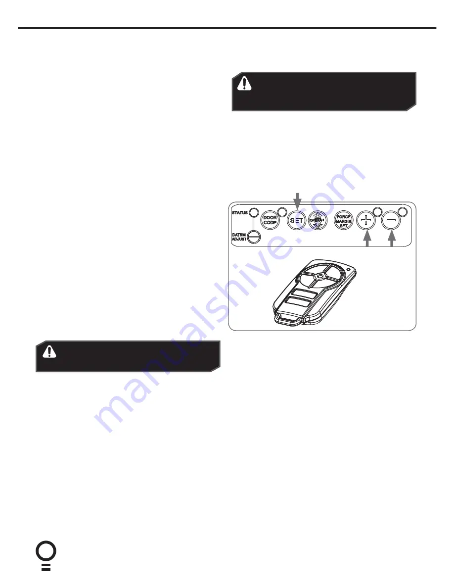
11. Setting the Travel Limits

Initial Preparation: 

a. With the door at the half way position and the opener 

engaged, switch power on to the opener. The red MINUS 

(-) LIMIT LED will be flashing.

b. Press and hold the MINUS (-) button - the door should start 

closing.

NOTE:

 If the door opens, release the MINUS (-) button and 

press the OPERATE button once to change the motor’s 

direction.

Set the Limit Positions:

The Limit Positions can vary due to site conditions, such as uneven ground. When setting the Close limits, ensure the position 

is when the door makes first contact with the ground. Alternatively for the Open limits the position should be at the height of 

the garage opening.

WARNING! In setting the close limit position, do 

not force the door into the floor with excessive 

force, as this can interfere with the ease of 

operation of the manual release mechanism.

a. Press and hold MINUS (-) button until the door reaches your 

desired close limit position. The rubber strip at the bottom 

of the door should form a good seal with the ground. 

b. Release the MINUS (-) button when the door is near the 

desired closed position. Single presses of the MINUS (-) 

button will inch the door closer to the ground.

c. If the door overshoots press the PLUS (+) button to move 

the door in the open direction.

d. When the door is at the desired close position, press the 

SET button, the PLUS (+) LIMIT LED will now flash.

e. Press and hold the PLUS (+) button until the door reaches 

your desired open limit position. Single presses of the PLUS 

(+) button will inch the door open.

f.  If the door overshoots press the MINUS (-) button to move 

the door in the close direction.

g. When the door is at the desired open position, press the 

SET button.

WARNING! The door will automatically close, 

open and close again after the next step. Ensure 

that nothing is in the door’s path.

h. The door will now automatically close and open to calculate 

the safety obstruction settings.

Resetting the Door Limit Positions

Limit positions can be deleted by:

a. Press and hold MINUS (-) button for six (6) seconds until the 

MINUS (-) LIMIT LED flashes quickly.

b. Release the MINUS (-) button.

NOTE: If no action is taken within 30 seconds, the opener will 

return to normal operating mode and restore the original settings.

c. Follow steps a - f in Set the Limits Poisitions to set new limit 

positions.

Reset all Factory Defaults

a. Turn power to the opener off.

b. Press and hold the SET Button.

c. Turn power on while holding the SET button. 


Continue to hold until all LED’s are off.

d. This will NOT erase transmitter codes stored in 

memory.

Summary of Contents for GDO-8 ShedMaster

Page 1: ...Water Resistant Roll Up Door Opener Instruction Manual GDO 8 ShedMaster Doc 160074_00 Part 13457 Released 25 08 16 ...

Page 2: ...1 Adjusting Safety Obstruction Force 11 To Increase Force Pressure 11 To Decrease Force Pressure 11 To Recall Factory Set Force 11 To Recalculate Force Margins 11 14 Coding a Transmitter 12 Storing the Transmitter Code 12 Coding a Transmitter to Enable Vacation Mode 12 Coding a Transmitter to the Courtesy Light 12 Remotely Coding Transmitters 13 Erasing a Stored Transmitter Code 13 Erasing All Tra...

Page 3: ...ons Fall from ladder Ensure ladder is the correct type for job Ensure ladder is on flat firm ground that will take the weight without the legs sinking Ensure user has 3 points of contact while on ladder Crush injury from unsecured door Place a 2 metre exclusion zone around area under the door while it is unsecured Do not move under a door while it is on the door support or ladder Follow the instal...

Page 4: ...2 x PTX 5 Transmitters 4 1 x Weight Bar Fastner Bag 5 2 x Nilock Nut 6 2 x 3 16 x 1 2 flat washers 7 2 x Pan Head Screw M4 x 50 1 2 3 5 6 7 4 Screwdrivers Adjustable End Wrench Sockets and Wrench Pencil Rope Drill Towel Self tapping Screws and Washers M10 x 32mm Stepladder Door Stand or suitable prop 3 Tools Required ...

Page 5: ... the inside of the door bracket and 85mm to the wall 4 Setup Requirements The Opener a MUST BE installed in a dry position protected from weather Moisture or corrosion not covered by Warranty b Is factory set for RIGHT HAND SIDE installation from inside garage but capable of LEFT HAND SIDE installation c REQUIRES properly earthed 3 pin single phase power within an arms length of door and at a suit...

Page 6: ... Pan Head Screw 7 and the two 2 Flat Washer 6 and the two 2 M4 Nilock Hex nut 5 d Check that the door is still balanced and smooth If not then the door may require servicing 4 2 7 5 Door Preparation Prepare the Door a Clean the guides if there is any oil or wax present using a suitable white spirit The only lubricant suitable for use on door guides is silicon spray DO NOT use WD 40 RP 7 petroleum ...

Page 7: ...r a At the end opposite to where the opener will be fitted check that the U bolt which holds the door axle to the bracket is tightened securely b Open the door completely and tie rope around the door roll Do not tie the rope too tight as damage to the curtain may ensue This will stop the door unrolling when taken off the bracket c At the end where the opener is to be fitted support the door with a...

Page 8: ...r rotates freely by pulling the string handle down there will be a click to disengage opener Then move the forks from side to side by hand c Slide the opener over the door axle and into the drum of the door as shown d Push the opener in as far as possible without interfering with the curtain SO ONE OF THE DOOR DRUM S WHEEL SPOKES IS BETWEEN THE OPENER S DRIVE FORKS e Raise the door off the door st...

Page 9: ... slowly until the yellow status LED just illuminates NOTE If the status LED is already illuminated when power is connected then turn the datum adjust screw until the LED goes off then turn back one notch to illuminate again WARNING The safety obstruction detection system is inoperable if the MINUS and PLUS buttons are used to drive the door and travels limits are not set 10 Setting the Datum ...

Page 10: ...he door closer to the ground c If the door overshoots press the PLUS button to move the door in the open direction d When the door is at the desired close position press the SET button the PLUS LIMIT LED will now flash e Press and hold the PLUS button until the door reaches your desired open limit position Single presses of the PLUS button will inch the door open f If the door overshoots press the...

Page 11: ...extreme temperature changes To Increase Force Pressure a Hold down the FORCE MARGIN SET button b While holding the FORCE MARGIN SET button press the OPEN button Each press will increases the force margin c The PLUS LIMIT LED will flash each time the PLUS button is pressed to indicate an increase in force d If the PLUS LIMIT LED flashes continuously when the PLUS button is being pressed this indica...

Page 12: ...press it again and hold will beep two times on second press e Press one of the four 4 buttons on the transmitter for two 2 seconds pause for two 2 seconds then press the same button again for two 2 seconds f Release DOOR CODE button g Press and hold the transmitter button for six 6 seconds to set Vacation Mode The door code LED will stay lit while Vacation Mode is active h To reset Vacation Mode p...

Page 13: ...ng a Stored Transmitter Code a Select the transmitter you want to delete b Press and hold the DOOR CODE BUTTON c Press the transmitter button you would like to delete for two seconds pause for two seconds press again for two seconds and then release d Release the DOOR CODE BUTTON The code should now be deleted Confirm this by pressing the transmitter button the function e g door opening should not...

Page 14: ... tension and can cause serious personal injury DO NOT attempt any garage door adjustment DO NOT use if repair or adjustment is needed Call for a professional garage door service CAUTION Emergency access If your garage has no pedestrian entrance door an emergency access device should be installed This accessory allows manual operation of the garage door from outside in case of power failure Entrapm...

Page 15: ...easy to operate No more than 15 kg of force should be required to disengage the door using the manual release cord If excessive force is required reset the close limit position Section 11 Resetting Door Limits 17 Operating your Opener To Operate the opener a Press the programmed transmitter button until your door begins to move usually 2 seconds Make sure you can see the door when you use the tran...

Page 16: ... on when the open limit position has been reached 5 DOOR STATUS LED Yellow Illuminates when Service is due 6 MINUS LED Red Illuminates and flashes as the door opens closes and remains on when the close limit position has been reached Door Status Indicators PLUS LED green MINUS LED red Beeper Open On Close On Opening Flashing Closing Flashing Door travel stopped Flashing Flashing Door obstructed wh...

Page 17: ... 12kg Receiver type Multi frequency UHF FM 433 47 433 92 434 37MHz Receiver code storage capacity 8 X TriocodeTM 128 4 button Transmitters Coding System TrioCodeTM 128 Type Coding type Code Hopping Number of code combinations Over 100 billion random codes Transmitter battery CR2032 3 Volts Courtesy light Light Module Optional Network connectivity Not Available Note Intermittent operations may occu...

Page 18: ...restricted Variations are normal depending on conditions e g temperature or external interference The battery life is exhausted Position of the transmitter in the motor vehicle Make sure you can see the door when you use the transmitter Check the battery status by pressing a button flashing or no light requires battery to be changed Aim the transmitter through the windscreen The door reverses for ...

Page 19: ...ut 10 15 secs then reconnect power If Red LED is flashing limits are not set Reset Limits 21 Troubleshooting If You Need a Service Call If the opener needs a service please call the dealer who installed the garage door opener their contact details are usually on a sticker on the back of your garage door For product assistance contact 1300 133 944 within Australia BEFORE CALLING you should have the...

Page 20: ...l benefits WARNING Prior to disposal recycling or collection all battery terminals must be securely insulated with a non conductive material to prevent any two batteries from short circuiting and generating heat during storage or transport Battery terminals may be insulated with electrical tape or batteries may be individually packaged in a non conductive material e g plastic bag or original packa...

Page 21: ...21 GDO 8 Instruction Manual 25 Service Schedule Year Approx Cycles Date Details 1 3 000 2 6 000 3 9 000 4 12 000 5 15 000 ...

Page 22: ...n fuses electrical surges power surges or power spikes e theft fire flood rain water lightning storms or any other acts of God f any installation configuration or use of the Product contrary to the instructions supplied with the Product g maximum continuous operating time exceeding 1 minute in 10 h the operating force exceeding 15kg 150 Newton when moving the door manually to the open or closed po...

Page 23: ...mitter Allows you to operate the opener within 10 metres of the door Ideal for mounting inside the house Wireless Keypad The entry keypad allows entry to the garage without using a transmitter 27 Optional Accessories There are a range of additional accessories for your added convenience and security Contact your Dealer for installation of these accessory items IMPORTANT NOTE Only TrioCode TM 128 T...

Page 24: ...Is your door sticking and hard to operate It may be time for a service for more details see section 22 For a service contact your dealer using the details below Dealer ...

Reviews: