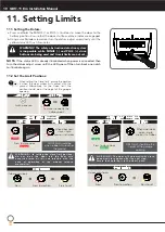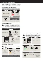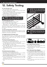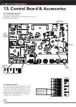
GDO-11 Ero Installation Manual
8
8. Perforated Angle
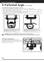
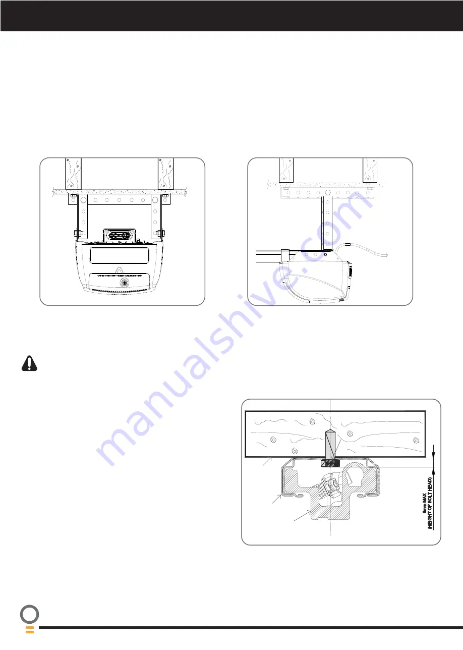
8.1 Attach Perforated Angle (not supplied) or equivalent
a. Measure across the ceiling from the centre point 3177mm (+/- 150mm) to find a supporting beam.
b. Create a perforated angle which best suits your site. Use a hack saw to cut the L shape metal strips. Secure the perforated
angle to a supporting beam using diagrams shown below.
c. Raise the drive unit to the ceiling mounted perforated angle and secure with M8x20mm screws and nuts (not supplied). Strips
should not extend more than 18mm below centre of drive unit mounting holes.
d. To prevent moisture on the C-rail running into the powerhead it is recommended a strip of silicon sealant is placed across the
top of the C-rail just before the opener.
Ceiling Beams that run towards the door requires:
1 x perforated L shape metal strip and
2 x shorter perforate L shape metal drop down strips..
Ceiling Beams that run parallel to the door requires:
2 x perforated L shape metal strips and
2 x shorter perforate L shape metal drop down strips..
(Not supplied)
Drill hole at centre of
track (recommended
bolt size M6 or M8)
Ceiling
Aluminium rail
Shuttle VP2 assembly
8.2 Alternative Mounting Option
(for One piece door without track (Tilt Door / J-Type))
The opener can be fastened to the roof by driving a bolt
through the C-Rail into a structural timber support. The bolt
head’s height must not exceed 6mm.
WARNING! The perforated angle MUST be securely fastened to a structural support.
The installer MUST select and use fasteners appropriate to the material into which they are being fixed.


