


NAM-TRS372-MT-EN-C
p32/38
The information in this document is the property of Automatic Systems and is confidential. The consignee withholds from using it for anything other than the use of the products or the execution of the
project to which they belong and withholds from communicating it to third parties without prior written agreement from Automatic Systems. Document subject to change without prior notice.
GROUP
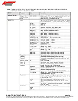
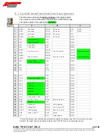
Parameter
Values
Description
OPTIONS
Code
-32768 to 32767
Code giving access to the Technician or Constructor level
parameters..
Language
Deutsch
Choice of the menu language: German.
Français
Choice of the menu language: French.
English
Choice of the menu language: English.
Idle Fct Picto
Off
Choice of display of the function pictogram when it is at rest:
off.
Red
Choice of display of the function pictogram when it is at rest:
red cross.
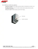
Thermostat °C
-10 to 100
Temperature beneath which the heating element is
engaged.
Electro Heating
Activated
Activates the electromagnets when the temperature
descends below the limit set at the “Thermostat °C”, which
maintains some warmth in the immediate environment of the
electromagnets.
Deactived
Heating by electromagnets deactivated.
Memo reader A
Yes
Storage by the reader of the Open commands given in
Direction A.
Memo reader B
Yes
Storage by the reader of the Open commands given in
Direction B.
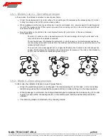
Electromagnet A
A4
Assembly of the electromagnet used for Direction A:
mode 4 (= locked when not powered).
A5
Assembly of the electromagnet used for Direction A:
mode 5 (= unlocked when not powered).
Electromagnet B
B4
Assembly of the electromagnet used for Direction B:
mode 4 (= locked when not powered).
B5
Assembly of the electromagnet used for Direction B:
mode 5 (= unlocked when not powered).
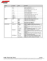
Fct Reader
Combined Mode
This operating mode combines the following two modes. If
an impulse is given, the apparatus functions in impulse
mode, if not it functions in maintained mode. Any signal that
occurs before detection of the limit switch or the end of the
no-passage time-out is regarded as an impulse.
Hold Mode
Passage managed by the reader: the passage is freed for as
long as the input reader is activated.
Pulse Mode
Passage managed by the AS1300: each reader impulse,
which can be memorized, frees the access for a passage. As
soon as the passage is carried out, the obstacle is locked.
Reader NO
Yes
Reader operation in Direction A and B (active in high status):
signal NO (Normally Open).
No
Reader operation in Direction A and B (active in low status):
signal NC (Normally Closed).
No Pass Limit
0 to 1000
Maximum number of consecutive no-passages before
indicating that the limit switch is defective.
TEST
Test Mode
Wiring
Wiring check of the AS1300 outputs.
Alternate Mode
Alternation of the following two modes.
Direction B
Successive lockings/unlockings of Direction B passage.
Direction A
Successive lockings/unlockings of Direction A passage.
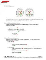
Communication
Menu
Sending of complete menu to external PC.
Stack Watch
Sending of stack values to external PC.
Diag. Extract.
Sending of diagnostic table to external PC.
Param. Extrac.
Sending of parameter values to external PC.
DATE & TIME
Year
0 to 99
Setting of year
Month
1 to 12
Setting of month
Day
1 to 31
Setting of day
Hour
0 to 23
Setting of hour
Minute
0 to 59
Setting of minutes
Second
0 to 59
Setting of seconds


