


NAM-TRS372-MT-EN-C
p17/38
The information in this document is the property of Automatic Systems and is confidential. The consignee withholds from using it for anything other than the use of the products or the execution of the
project to which they belong and withholds from communicating it to third parties without prior written agreement from Automatic Systems. Document subject to change without prior notice.
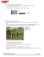
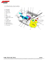
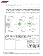
2.5.8. Heel guard assembly (option)
1. For each mobile comb, remove the plug (G) from the tube that is closest to the ground.
2. Slide the heel guard (E) onto the tube.
3. Close by means of provided plug (F) (larger): article EMB-E-0010418.
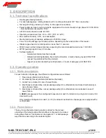
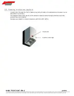
2.6. Electrical connections
Power supply and command cables are provided by the user and are described in the implementation
drawing.
If the command cables are different from the ones recommended, they must be separated from the power
supply cables in order to avoid interference. Thus, they must run through different uprights.
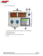
1.
Connect the power supply to the breaker as shown.
Protect the upstream line with a 16-A breaker.
2. Connect the options (card readers, etc.) according to the electrical diagrams.
3. Engage the circuit breaker.
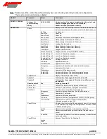
4. Set the control board according to the added options ("OPTIONS" group).
5. Send a passage command and verify that the turnstile is working properly: unlocking, rotation of the obstacle,
locking.
120 V
Ground
Neutral
E
G
F


