autogaz AC STAG-100 Installation & Programming Manual Download Page 9


Page 9 of 17 


On the oscilloscope you can see basic STAG controller signals:   
lambda sensor, lambda simulation, TPS and actuator positions . 

Below the graph, there is a signal table. 

You can enable each graph and select its colour in the “Graph” column.  

Apart from the oscilloscope, signal values are displayed in the “Values” column and visualised as line 

graphs. 


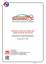
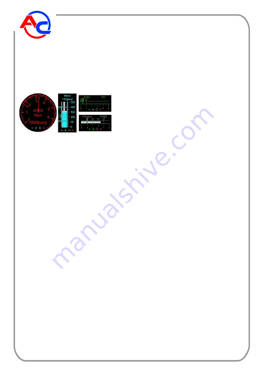
Gauge windows – display signals, it is possible to change 

their position, size and shape ([-][+][O] buttons) 


Additionally, in V1.77 version the windows of additional gauges are also accessible. They are displayed 

by clicking a list below the “Gauges” button or by double-clicking relevant line in the signal table. It is 

possible, separately for each such window, to change its position (using left mouse button), size ([-] [+] 

buttons), shape ([O] button) and close ([X] button).  


KEYBOARD SHORTCUTS 


F1 

- full function switch names / abbreviations 

F2 

- screen SETTINGS 

F3 

- screen PARAMETERS 

F4 

- screen CONFIGURATION 

F6 

- screen VERSION 

F7 

- parameter table activation for the screen PARAMETERS 

F8 

- working mode change GASOLINE / AUTO / LPG 

NOTE: working mode change is possible also with mouse 

F9 

- font change 

F10 

- start of communication with the controller 


QUICK CHANGE OF PARAMETERS 


To change parameters and their values it is possible to use mouse buttons through 

clicking on selected parameter as well as keyboard keys: 

UP / DOWN 

- parameter change 

RIGHT / LEFT 

- parameter value change 


Summary of Contents for STAG-100

Page 1: ...150 LAMBDA SENSOR CONTROLLER INSTALLATION PROGRAMMING MANUAL version V1 77 V1 79 Manufacturer AC Sp ka Akcyjna 15 181 Bia ystok ul 42 Pu ku Piechoty 50 Poland tel 48 85 7438148 fax 48 85 653 8649 www...

Page 2: ...pply is switched on green LED shines constantly The LPG output is controlled with a actuator and depends on lambda sensor indications All STAG 50 100 150 parameters are set with an external tester or...

Page 3: ...he working mode switch function 50 100 150 CABLE COLOUR DESCRIPTION 11 15 11 BLACK GND 1 2 1 BLACK RED 12 V BATTERY 15 13 15 RED 12 V IGNITION SWITCH 19 14 19 BROWN RPM 5 12 V PULSES 14 1 14 BLUE LPG...

Page 4: ...Page 4 of 17 STAG 50 installation diagram...

Page 5: ...ector power supply point 20 Emulation of injections Emulation of multi point injector yellow white green 12 power supply of all injectors 100 Emulation of injections Fuel pump cutoff yellow white gree...

Page 6: ...R SUPPLY 9 YELLOW BLACK INJECTOR 1 COMPUTER 3 GREEN INJECTOR 2 POWER SUPPLY 10 GREEN BLACK INJECTOR 2 COMPUTER 4 RED INJECTOR 3 POWER SUPPLY 11 RED BLACK INJECTOR 3 COMPUTER 5 BLUE INJECTOR 4 POWER SU...

Page 7: ...appears the screen PARAMETERS and transmission percentage indicator If after a few trials the software cannot establish communication with the controller then instead of the transmission percentage i...

Page 8: ...auges window controller parameters readout grid on start stop oscilloscope oscilloscope time base change save visualisation file open visualisation file oscilloscope on off graph colour change save co...

Page 9: ...utton or by double clicking relevant line in the signal table It is possible separately for each such window to change its position using left mouse button size buttons shape O button and close X butt...

Page 10: ...f actuator steps proportional to accelerator s pressing WEAKENING number of actuator steps proportional to accelerator s loosing ACTUATOR SPEED actuator speed during enrichment weakening OPEN addition...

Page 11: ...mulation pulse upper course TIME LO duration of simulation pulse lower course TIME OFF total time of pauses between pulses groups 0 no pause PULSE NUMBER number of pulses within a group 0 no groups DI...

Page 12: ...er switching on the ignition switch while working with gasoline LPG LEVEL SENSOR depending on LPG level sensor voltage thresholds for activation of relevant LEDs indicating LPG level FAULTS DETECTED B...

Page 13: ...be added for individual rpms CONFIGURATION GASOLINE Start controller configuration for gasoline with the key GASOLINE According to dialog window commands proceed as follows start the engine set workin...

Page 14: ...e use of CONFIGURATION LPG function Adjustment should be done using menu PARAMETERS start the engine in gasoline mode and wait for proper lambda sensor operation set the controller for GASOLINE mode C...

Page 15: ...software modification After connecting the controller to a PC the new window VERSION appears If the folder containing the program AcLpgWin exe includes also a batch program of the STAG 50 100 150 cont...

Page 16: ...d successfully appears press OK The controller performs restart and begins to work with the new version of the software If the programming process is interrupted or there are some errors diagnostic so...

Page 17: ...e disconnected frame Type of changeover gasoline LPG rpm up rpm down rpm TPS Time of simultaneous operation gasoline LPG 0 1 020 s Temperature of switchover gasoline LPG 60 185 C Switchover rpm 1000 1...

Reviews: