background image


18 


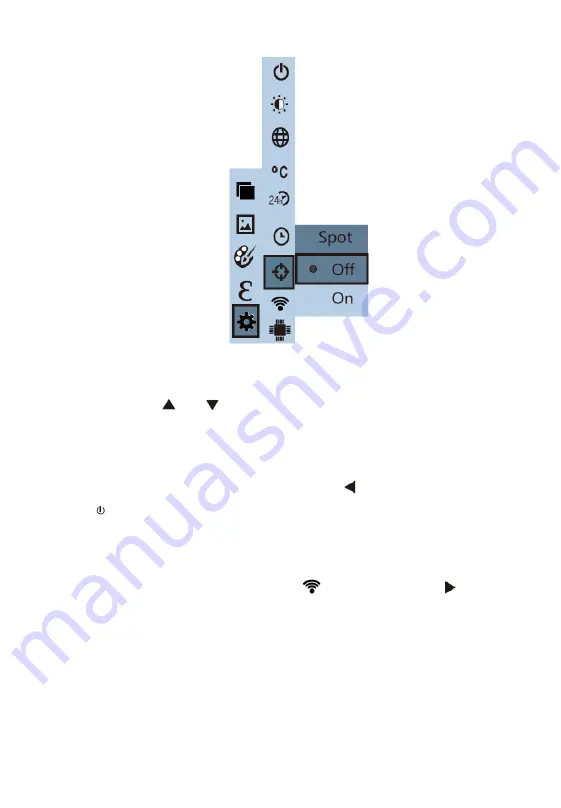
Figure  5-8 Cursor Setting 


Press the "

" or "

" key to select "Off"  or "On" to disable or enable 

the cursor. Then press the "SELECT/ENTER" key to determine the 

selection. 


After  the setting is completed, press the "

" key to return. Press the "

/MENU" key to exit the menu. 

Wi-Fi  Setting 

As shown in Figure 5-9, after selecting "

" (Wi-Fi), press the "

" key to 

enter the Wi-Fi option. 

Summary of Contents for MaxiIRT IR100

Page 1: ...e latestinformation available atthe time of printing Autel reserves the right to make changes at any time without notice While information of this manual has been carefully checked for accuracy no guarantee is given for the completeness and correctness of the contents including but not limited to the product specifications functions and illustrations Autel will not be liable for anydirect special ...

Page 2: ...antle assemble or remodel anypartofthe product Repair ofthe productshouldbe made by technical personnel designated byAutel Company Avoid damage to the detector of the product NOTE Do NOTexpose the productthe sun or other strong lightsources Otherwise it may damage its detector Product crack When the productworks lightcrack will be heard everyseveral seconds This is normal phenomenon when the lens ...

Page 3: ... may cause overheating deformation or fire Ensure that the plug of the adapter is inserted into the specified power socket The adapter plug may vary by region Make confirmation whether the specification of the adapter is consist with the specification of electric appliances in your region Otherwise this may cause overheating of the equipment electric shock fire chemical leakage inside the battery ...

Page 4: ... the enclosure of the device Such operation maydamage the enclosure ofthe device The product temperature may increase after charging for a long time You may feel scorching heatwhen touching the sensors Problem caused by water condensation Do NOT bring the instrument into low temperature environment from high temperature environment or from low temperature environment to high temperature environmen...

Page 5: ...should be placed at a cool and dry environment if it not been used for a long time If the product installed with battery is stored for a long time charging should be made regularly Otherwise the battery will run out and its service life will be shortened ...

Page 6: ...LENSMAIN TENANC E 3 CHARGING THE BATTERY AND DESCRIPTION 4 3 PRODUCT DESCRIPTION 1 FUNCTION DESCRIPTION 1 DISPLAY DESCRIPTION 3 TECHNICAL SPECIFICATIONS 4 4 GETTING STARTED 6 INITIAL OPERATION 6 5 MENU OPERATION 8 IMAGE OVERLAPPING 8 IMAGE 9 COLOR PALETTE 10 EMISSIVITY 12 SETTINGS 14 6 TROUBLESHOOTING 21 7 WARRANTY 22 LIMITED ONE YEAR WARRANTY 22 ...

Page 7: ...t Bold text is used to highlight selectable items such as buttons and menu options Example Tap OK Notes and Important Messages Notes A NOTE provides helpful information such as additional explanations tips and comments Example NOTE If there is no operation for longer than 6 seconds the image overlapping mode will be automaticallyexited Important IMPORTANTindicates a situation which ifnotavoided ma...

Page 8: ...earch in fire protection Personnel search and rescue in the fire and fire command Analyze the location of leak points in heat pipes and heating equipment and heat loss Determining the location ofthe heating fault of the operating train Security departmentnightmonitoring Overview This infrared thermal camera integrates surface temperature measurement and real time thermal image The traditional one ...

Page 9: ...ith soap water to clean the enclosure ofthe device instead of grinding additives isopropanol or solvent to clean The lens and screen should be cleaned with optical glass cleaner LensMaintenance Prevent damage ofthe infrared lens The lens is provided with refined anti reflection coating Clean the lens with care so as not to damage the anti reflection coating Use cleaner for lens maintenance such as...

Page 10: ...ryruns low the upper right ofthe screen will display Recharge productin time through a Micro USB port Pull off the USB cable after the product is fully charged To optimize the performance of lithium ion batteries Do not connect the battery to the charger for longer than 24 hours The infrared thermal camera should be charged for two hours atleast every three months so as to maximize the battery ser...

Page 11: ...1 Product Description Function Description Figure 3 1 Function Description Front 1 DisplayScreen 2 Menu Key On Off Key 3 Navigation Key Left ...

Page 12: ...2 4 Navigation Key Up 5 Selection Key Enter Key 6 Navigation Key Right 7 Navigation Key Down 8 Handheld Figure 3 2 Function Description Back 9 Micro USB open the cap for use 10 Visible LightCamera ...

Page 13: ...lue is displayed at the upper leftcorner of the screen The highest temperature cursor used to indicate the highest temperature position in the screen area It will move with the change of the highesttemperature point The cursor displays red The temperature value is displayed at the lower left corner of the screen The lowest temperature cursor used to indicate the lowest temperature position in the ...

Page 14: ... Adjustable from 0 01 to 1 00 Color palette rainbow iron oxide red cold color white hot black hot Temperature measurementrange 20 C to 450 C 4 Fto 842 F Measurementaccuracy 100 C 2 C 100 300 C 2 300 C 3 400 C 5 Storage capacity Built in 8G File format JPEG USB Micro USB 2 0 Power supply Built in chargeable 26650 battery Detachable Working time 3 4 hours Setting command Unit measurement language da...

Page 15: ...5 Item Description Product size 256mm 97 2mm 128 9mm Product weight 588g Working temperature 0 C to 45 C Storage temperature 20 C to 60 C Relative humidity 85 RH ...

Page 16: ...bienttemperatures Switching Between Infrared Thermal Image and Visible Image Press the or key to switch the degree of fusion between infrared thermal images and visible images the degree offusion is 0 25 50 75 and 100 respectively Image Capture Press the image capture key When the capture is successful the screen will display a promptsaying save photo Select Yes to save or No to delete the image P...

Page 17: ...ed to the computer by a Micro USB cable Read Images Open the USB protective cover as shown in Figure 3 2 Connect the product to a computer with the USB cable You may read or save the images to the computer You are suggested to use the included USB cable NOTE To disconnect the product from a computer pull off the USB cable after selecting pop out device safely to avoid causing file system damage an...

Page 18: ...re easily Image Overlapping Application Press the MENU key to enter the main menu and select Image overlapping in the main menu Press the SELECT ENTER key to enter the image overlapping adjustment mode Press the navigation keys up down left and right keys to perform the visible image shiftoperation Press the SELECT ENTER key to exit the image overlapping mode NOTE If there is no operation for long...

Page 19: ...ss the SELECT ENTER key The image overlapping parameters can be reset as shown in Figure 5 1 Figure 5 1 Resetting Image Overlapping Image View Image Press the MENU key to enter the main menu and select Image in the main menu Figure 5 2 Viewing Images ...

Page 20: ...or Palette option allows users to change pseudo color displayofthe infrared image Some color palettes are better suited for specific applications and can be set up as needed Five color palettes are available namely rainbow iron red cool color white hot black hot which work bestwith high contrastthermal and color contrastbetween high and low temperatureswill be provided Selectthe suitable color pal...

Page 21: ... Palettes Press the MENU key to enter the main menu and select color palette option and press the key to enter the color palette list Press the or keyto selectthe color palette Then press the SELECT ENTER key to confirm the selection Press to return Press the MENU keyto exit the menu ...

Page 22: ...ss objects is 0 6 Shiny objects have a lower emissivity value which is usuallysetto 0 3 atthe time of measurement A proper emissivity value is very important in measuring target temperatures The surface emissivity will produce giant impacton surface temperature measured bythe product Understanding the surface emissivitywill enable you to obtain correcttemperature measurement results Emissivity Set...

Page 23: ...e menu To define your own emissivity values select Custom and press the SELECT ENTER key to enter the editing state Press or to select the digit of the value to be changed press or to change the value When the modification is completed press the SELECT ENTER key to confirm then press to return Press the MENU keyto exitthe menu Emissivity Values of Common Materials Set up the emissivityfor the targ...

Page 24: ...14 Settings Press the MENU key and select the setting option in the main menu Press the key to enter the Settings submenu ...

Page 25: ...ss the key in the navigation key to enter the auto shutdown setting Three modes are available no auto shutdown auto shutdown in 5 minutes and auto shutdown in 20 minutes Intensity Setting After selecting brightness press the key to enter the brightness setting option Three modes are available low medium and bright ...

Page 26: ... After selecting unit press the key to enter the temperature unit option Two modes can be chosen Celsius and Fahrenheit Time Format Setting After you select time format press the key to enter the time format option Two modes can be chosen 24 hour and 12 hour time systems Time Setting As shown in the Figure 5 7 after selecting settime press to enter the time option ...

Page 27: ...gure to be changed Press the or keyto change the value After completing the change press the SELECT ENTER key to confirm After the time setting is completed press the key to return Press the MENU key to exit the menu Spot Setting Enable or disable the highestand lowesttemperature cursors As shown in Figure 5 8 after selecting cold hotspot press the key to enter the spotoption ...

Page 28: ...able or enable the cursor Then press the SELECT ENTER key to determine the selection After the setting is completed press the key to return Press the MENU key to exit the menu Wi Fi Setting As shown in Figure 5 9 after selecting Wi Fi press the key to enter the Wi Fi option ...

Page 29: ... is the same as the product serial No You may check the serial No on the camera cover or on the Wi Fi setting page After the mobile device is connected to the Wi Fi access the IP 192 168 230 1 on the mobile device s web browser to connectthe mobile device to the product On the mobile device you are allowed to set the color palette blending degree emissivity maximum minimum values language and sync...

Page 30: ...n the productas shown in Figure 5 10 Figure 5 10 Saving Images Through a Mobile Device Click Images in the upper leftcorner on the mobile device to enter theimage view Press an image to download it Long press an image to save it to the mobile device Click IR Stream to return to the video stream webpage as shown in Figure 5 11 Figure 5 11 Downloading Images Through a Mobile Device ...

Page 31: ...c power off after restarting IMPORTANT a Ifthe productmalfunctions repair or replacementwith new or good product will be made according to the condition after the productis inspected b One year warranty service is offered if quality issues are confirmed by warranty personnel under the following circumstances The product is operated according to requirements and relevant specification The productis...

Page 32: ...ted to the defect s The Companyshall notbe liable for anyincidental or consequentialdamages arising from the use misuse or mounting ofthe device Some states do not allow limitation on how long an implied warrantylasts so the abovelimitations may not apply to you This warranty does not apply to 1 Unable to show the original of effective warranty voucher 2 The damage caused in the process of install...

Reviews: