Austria Email ECO SWIFT Manual Download Page 14

14

E.2. - Menu sequence and menu structure

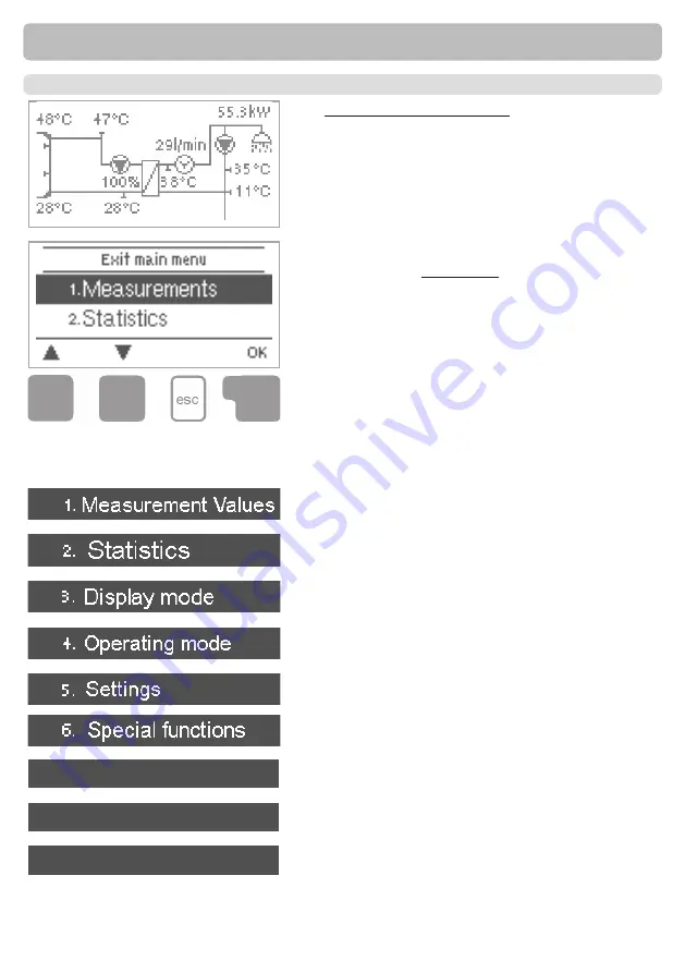
The graphics or overview mode appears when no 

key has been press for 2 minutes, or when the main 

menu is exited by pressing “esc“.

Pressing a key in graphics or overview mode takes 

you directly to the main menu. The following menu 

items are then available for selection there:

Current temperature values with explanations

Function control of the system with operating hours, 

etc. 

Select graphics mode or overview mode 

Automatic mode, manual mode or switch unit off

Set parameters needed for normal operation

Program selection, clock, etc. 

Functions to prevent damage to system and user.

Against unintentional setting changes at critical 

points

For diagnosis in the event of an error

Operation

7. Protective functions

8. Menu block

9. Service Values

Summary of Contents for ECO SWIFT

Page 1: ...ECO SWIFT ECO SWIFT E ECO SWIFT EZ FRESHWATER STATION CONTROLLER MANUAL...

Page 2: ...calibration 22 4 6 Zone valve 22 4 12 Comfort 22 5 Protections Protective functions 23 5 1 Antilegionella 23 5 2 Limescale Protection 24 5 3 Discharge Protection 24 5 4 Seizing protection 24 6 Specia...

Page 3: ...ssential that you read this These installation and operating instructions contain basic instructions and important infor mation regarding safety installation commissioning maintenance and the optimal...

Page 4: ...accessories Use of the device for other than its intended purpose Operation above or below the limit values listed in the specifications Force majeure Changes additions to or conversion of the unit ar...

Page 5: ...l min 40 l min VFS2 40 5 l min 100 l min VFS5 100 10 l min 200 l min VFS10 200 0 0 6 bar 0 1 bar 0 1 6 bar 0 2 5 bar 0 4 bar 0 6 bar 0 10 bar Permissible cable length of sensors and appliances other...

Page 6: ...Analysis and monitoring of the system by means of statistical graphics etc Extensive setting menus with explanations Menu block can be activated to prevent unintentional setting changes Resetting to p...

Page 7: ...mplete The controller does not replace safety devices under any circumstances Depending on the spe cific application additional system components and safety components may be mandatory such as check v...

Page 8: ...s when doing so 4 Hold the lower part of the housing up to the selected position and mark the 3 mounting holes Make sure that the wall surface is as even as possible so that the housing does not becom...

Page 9: ...cables Feed temperature sensor cables only into the left hand side of the unit and mains voltage cables only into the right hand side Caution Caution Caution Installation The customer must provide an...

Page 10: ...s Fig C 3 1 4 Open the terminals using a suitable screwdriver Fig C 3 2 and make electrical connections on the controller 5 Connect the flow sensor to the socket on the board Fig C 2 3 6 Refit upper p...

Page 11: ...ended to a maximum of 10m using a cable with a cross section of at least 0 75mm Sensor cables for the VFS sensor can be extended to 3m Make sure that there is no contact resistance Example Connections...

Page 12: ...ow voltage max 12VAC DC connection in the left hand terminal compartment Terminal Connection for S1 Circulation opt S2 Cold water optional see box below S3 Primary flow opt S4 Storage top opt S5 stora...

Page 13: ...menu If applicable there will be a request for confirmation as to whether the changes which have been made should be saved The function of each of the other three keys 4 is shown in the display line...

Page 14: ...able for selection there Current temperature values with explanations Function control of the system with operating hours etc Select graphics mode or overview mode Automatic mode manual mode or switch...

Page 15: ...you should make the necessary settings in the following sequence Menu 6 Special functions clock Additional functions Menu 5 Settings complete Finally menu 4 2 under operating mode Manual should be us...

Page 16: ...the callibration process a text is shown that the flow rate is measured and no tapping is allowed After confirmation the circulation pump is switched off and the controller is waiting until the flow...

Page 17: ...r incorrect temperature sensor If the cables are too long or the sensors are not placed optimally the result may be small deviations in the measurement values In this case the display values can be co...

Page 18: ...tion Statistics 2 1 Operating hours HW Display of operating hours of the relays connected to the controller 2 2 Operating hours circ Display of operating hours of the circulation pump connected to the...

Page 19: ...1 Automatic Operating modes Danger Whenoperatingmode Manual isactivated thecurrenttemperaturesandtheselected parametersarenolongerconsidered Thereisadangerofscaldingorseriousdamage to the system The...

Page 20: ...maintain a constant temperature in the cir culation by controlling the speed of the hot water pump Danger Temperature values which are set too high can lead to scalding or damage to the system Scaldin...

Page 21: ...s is reached at the circulatiopn sensor Always on Circulation pump is switched on in set periods 4 4 2 Circ Tmin Minimum temperature at sensor S2 If the temperature drops below Circ Tmin and the circu...

Page 22: ...e During calibration a message appears that the flow rate is detected and no tapping is allowed in the meantime After confirmation the circulation pump switches off and the controller waits until the...

Page 23: ...s which can lead to scalding and damage to the system Caution This anti Legionella function does not provide complete protection against Legionella because the controller is dependent on sufficient en...

Page 24: ...ction If the temperature in the primary circuit is not always guaranteed to suffice this function is used With this function activated When no storage sensor is connected If the setpoint temperature i...

Page 25: ...the pumps data sheet 0 10V Speed control of e g High efficency pumps by 0 10V signal PWM Speed control of e g High efficency pumps by PWM signal 6 1 2 Pump In this menu preconfigured profiles for var...

Page 26: ...ol R1 R2 Caution Caution The indicated percentages are guide values that may vary to a greater or lesser extent depending on the system pump and pump stage The indicated percentages are guide values t...

Page 27: ...um temperature If this temperature is undershot storage heating is turned on even outside the set periods for the storage heating 6 5 2 2 SH Setpoint Temperature Taget temperature at thermostat sensor...

Page 28: ...switched on 6 5 4 1 Parallel operation V1 See 6 5 4 Parallel operation V1 6 5 4 3 Followup time This menu determines how long after the switch off of R1 or R2 the parallel relay is switched off 6 5 5...

Page 29: ...ot an error message is displayed and the relay is switched on 6 9 4 Pmax Maximum pressure If this value is exceeded an error message is displayed and the relay is switched on 6 8 Signal V2 With this f...

Page 30: ...Pressing the esc more than once takes you back to the selection mode thus cancelling the commissioning help see also 5 1 Caution May only be started by a specialist during commissioning Observe the ex...

Page 31: ...troller s clock changes automatically to and from DST DST Daylight Saving Time 6 14 Daylight saving time When this function is active the controller s backlight is automatically switched off when no b...

Page 32: ...if necessary 1 Measurement values 2 Analysis 3 Display mode 8 Menu lock 9 Service values To lock the other menus select Menu lock on To enable the menus again select Menu lock off Menu lock 7 1 Menu...

Page 33: ...ed for remote diagnosis by a specialist or the manufacturer in the event of an error etc Caution Enter the values at the time when the error occurs e g in the table Themenucanbeclosedatanytimebypressi...

Page 34: ...elect the language for the menu guidance This is queried automatically during initial commissioning The choice of languages may differ however depend ing on the device design Language selection is not...

Page 35: ...the sensor the sensor input at the controller or the connecting cable is was defective Resistance table on page 5 This display appears automatically after a mains failure because the time date have to...

Page 36: ...ernal source of the error e g pump and exchange it Then first recommission the controller and check the function of the switch outputs in manual mode as described under 9 2 Repairs and maintenance may...

Page 37: ...list and have the settings optimised if necessary Caution Performing maintenance Check the date and time see 11 1 Assess check plausibility of analyses see 7 Check the error memory see 7 5 Verify chec...

Page 38: ...ctions have been created with the greatest possible care thepossibilityofincorrectorincompleteinformationcannotbeexcluded Subject as a basic principle to errors and technical changes Notes Hydraulic v...

Reviews: