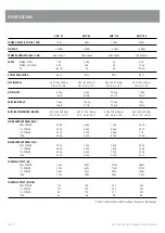


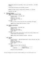


Values to be recorded
Value
Pass
Range
7a.
Bandwidth - low
<75Hz
7b.
Bandwidth - high
>20kHz
8.
Phase
Setup
Signal generator = 260mVAC, 1kHz
Signal in = XLR
Master pot = max (CW)
Output metering = 100Vout
Load = 80ohm
Procedure
Attach channel 2 of the CRO to the input. Make sure the CRO is being triggered by
the input. Look at each output on channel 1 of the CRO. The CRO ground should be
connected to the common both for the low impedance outputs and the line outputs.
(P/F) The signals on the CRO shall be in phase for all outputs (100V, 4
Ω
).
9.
Current Limit
Setup
Signal generator = 260mVAC, 1kHz
Signal in = XLR
Master pot = min (CCW)
Output metering = 100Vout
Load = 80ohm
Procedure
Change the load to 40ohms. Increase the signal such that at ~65VAC you can see
the overload protection coming on with a rounding of the sine wave. If it is there
then reduce the voltage to 30VAC out. Short the unit for ~10sec. Release the
shorting link and check for the output.
(P/F) The output shall be reading 30VAC +/-1V.
10.
Noise floor / SNR
Setup
Signal in = none
Master pot = max
Output metering = 100Vout
Load = 80ohm
Procedure
Put dummy lid on. Check for Hum & Noise.
(P/F) The output shall be reading < 3.2mVAC (-90dBr ref 100V).
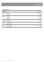
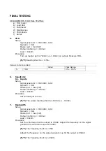
Values to be recorded
Value
Pass
Range
10.
Noise floor
0mV – 3.2mV
11.
Fan/Thermal check
Setup
Signal generator = 260mVAC, 1kHz
Signal in = XLR
Master pot = max (CW)
Output metering = 100Vout


