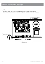


(P/F) Slowly adjust the preset PR1 so that you get 4.5mVDC (+/-0.5mVDC)
reading.
Check Quiescent Voltage across all Emitter resistors.
(P/F) The emitter resistor voltages shall be 4.5mVDC (+/-2.0mVDC).
[Setup for next test]
4.
Initial AC Checks :
4.1.
Signal check and gain of amp
Setup
Signal generator = 260mVAC, 1kHz
Signal in = XLR
Master pot = max (CW)
Output metering = 4ohm out
Load = 4ohm
Procedure
Turn up volume control to full. Watch for irregularities with output.
(P/F) Output voltage shall be 21.9VAC +/-2VAC.
4.2.
Emitter current check
Setup
Signal generator = 260mVAC, 1kHz
Signal in = XLR
Master pot = max (CCW)
Output metering = 4ohm out
Load = 4ohm
Procedure
Set output to 15VAC using master volume control. Check voltage across
emitter resistors of power devices.
(P/F) Voltage shall be between 150mVDC – 250mVDC.
4.3.
Outputs
Setup
Signal generator = ~260mVAC adjusted for 21.9V out with pots max, 1kHz
Signal in = XLR
Master pot = max (CW)
Output metering = 4ohm out
Load = 4ohm
Procedure
Using a multimeter check the following:
(P/F)
Pass
Range
100V line
90VAC – 110VAC
Measure on the terminal block.
Remove all inputs and connections. Attach tested tag. Turn all volume pots to min.


