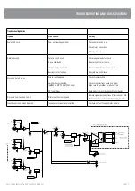


Test Procedure
VISUAL INSPECTION STAGE
1.
Physical checks
•
All screws for tightness (esp. bridge rectifier and transistor bolts), referring to the
torque setting of the manufacturing tools
•
Capacitors for polarity
•
Earth connection for good contact, using multimeter (XLR GND to AC earth)
•
Power transistors for shorts to heat sink using a multimeter
•
All wiring points for good contacts (soldering and crimping)
PRETESTING
PRE TESTING SETUP REQUIREMENT
a)
Oscilloscope
b)
Variac
c)
Multimeter
d)
Load [4ohm]
e)
Signal generator
f)
Phantom power jig
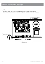
2.
Set up amplifier for test :
2.1.
Fuse check
2 x AC fuses (2A), 20x5mm
1 x DC fuses (8A), 20x5mm
2.2.
Connections
Connect amplifier to:
Variac (0Vac)
Signal generator (mic1, no signal)
Resistive load (4ohm on 4ohm terminal) with meters/oscilloscope
2.3.
Reset controls:
Volume control to minimum
PR1 (preset) on the amplifier PCB CCW
3.
Power up :
Turn on power switch and adjust voltage to 230VAC. Watch current meter for excess
current draw.
(P/F) Current shall not exceed 0.5Aac.
3.1.
Voltages
Measure the following DC voltages with a multimeter referenced to mains safety
earth or the chassis.
(P/F)
Pass
Range
DC power supply
47.5VDC – 55.0VDC
Input PCB rail (ICp8)
11.0.0VDC – 13.0VDC
Input PCB ½rail (ICp1) 5.0VDC – 6.0VDC
Input PCB gnd (ICp4)
-0.1VDC – +0.1VDC
3.2.
Bias setup
Put a multimeter across an emitter resistor.


