AUSTRALIAN MADE GREAT MATE Installation And Setup Instructions Download Page 19

© 2012 G Force Automatic Gates All Rights Reserved 


Warranty & Returns 

POLICY 


GENERAL 

Automatic  Gate  products  are 

covered  by  the  manufacturer’s  warranty  which  covers  defects  in  materials  and  workmanship  for  the 

Warranty  Periods  stated  below.  This  warranty  is  additional  to  any  applicable  statutory  requirements,  subject  to  the  exclusion s  and 
limitations stated below. 


Product is deemed to be warranted from the date of initial purchase from G-Force Automatic Gates. Proof of purchase is required when 
applying for warranty claims. 


Warranty is offered on a Back-to-

Base Warranty basis. Where issues can’t be resolved by your Installer or local Reseller in person, or by  

Staff over the phone, product will need to be returned at Customer Cost to for assessment, repair or replacement. 
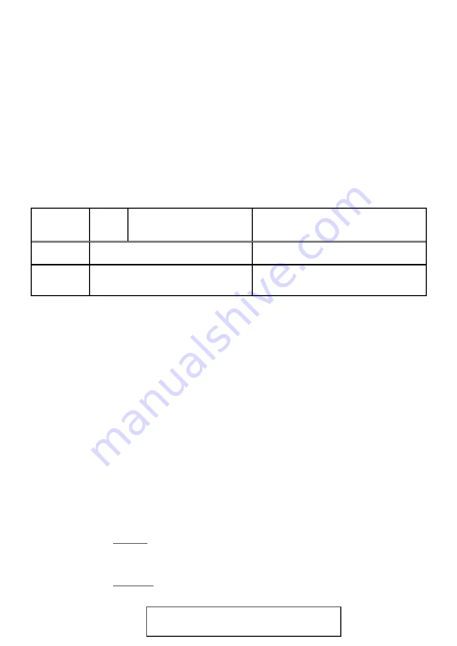
 

year 


DIY 

Gate Kits 


Applicable Kits: 

FG 5, SW 5, DSW 5, SL2000, 

year 

Visitor Access & Hardware 

Such as: 

Intercoms, Keypads, PE Beams, Loop Detectors, etc. 

month 

Spare Parts 

(exclusive of warranty replacements) 

Such as: 
Control Boards, Receivers, Remote Controls, Gears, 
Limit Switches, Brushes, etc. 


Warranty Periods 

Exclusions & Limitations 

The warranties stated herein do not cover damage, malfunction or service failures caused by: 

Failure to follow G-Force or Product Installation, Operation or Maintenance Instructions 

Repair or modifications to your G-Force product by someone other than a G-Force Service Technician, Authorised Installer or 
Reseller 


Abuse, misuse or negligent acts 


Batteries or Fuses supplied with your G-Force product (inc Handset batteries) 


Power failure surges, lightning, fire, water damage, pest damage, accidental breakage, actions of third parties and other events 
or accidents outside of G-

Force Automatic Gate’s reasonable control and not arising from normal operating conditions 


G-Force Automatic Gates is not responsible for any special, incidental, consequential or punitive damages arising from the use 

or 

Request 

To lodge a claim, contact G-Force Automatic Gates on 1800 111 930 for assignment of an 

RMA No. 

(Returns Material Authorisation No.). This number should be recorded on each box of returned goods to 
enable in-house tracking of your goods 


Return Goods 
to G-Force 

Goods are to be returned to G-

Force Automatic Gates at the Customer’s cost. G-Force will assess returned 

product within 7 days to determine the extent of warranty cover and likely repair costs 


Repair or Re- 
placement  of 
Goods 

In-Warranty 

Repairs will proceed as soon as practicable. The manufacturer’s offering the warranty 

reserves the right to repair or replace product at its discretion. It may, at its discretion, use new, remanufac- 
tured, or refurbished parts or products when repairing or replacing product. Replaced parts become the 
property of G-Force Automatic Gates. Repair costs and return freight of in-warranty repairs will be covered 
free of charge 

Non-Warranty 

Repairs will not proceed until you are notified of estimated Repair Costs, we receive authori- 

sation and payment details from you to proceed. Where product is deemed to be unrepairable, and you re- 


Summary of Contents for GREAT MATE

Page 1: ... 2012 G Force Automatic Gates All Rights Reserved GREAT MATE Double Swing Gate Motor Kit Solar Powered and 12V Low Voltage Installation and Set Up Instructions ...

Page 2: ...clear of the gate s and gate motor at all times Before attempting to service the gate motor or removing the cover turn off and or disconnect the power to the gate motor If you are unable to do this then we strongly recommend you call an electrician Care should be taken as there are moving components inside the gate motor that may cause damage or personal injury Keep any gate controllers out of rea...

Page 3: ...0mmside clearance from the gate hinge to allow the arms to rotate around during the opening of the gate We recommend 1 5mm twin active lighting cable for power supply wiring and 1mm figure 8 wire for wiring push buttons and other auxiliary items Place the gate motors on a suitable work bench Unpack the motors and remove the metal motor cover Visually inspect the motor to ensure nothing has moved d...

Page 4: ...ires from Terminals if Fitted Electric Lock Terminals Motor 2 Terminals Motor 1 Terminals Gate Direction LED s Open GREEN LED Close RED LED OPN Open Close Time Delay set push button OSC Auto Close Time set push button DIP Switch 1 DIP Switch 2 DIP Switch 6 DIP Switch 8 12V Power Out Terminals V positive terminal 0V Negative terminal Battery Lead Terminals RED Positive BLACK Motor Force Trim Pot Mi...

Page 5: ...anual release nut and bolt Push the DC motor away from the gears to disengage the motor and allow the gate drive arm to move by hand Pull the DC motor back towards the gears to engage Ensure the DC motor gear has meshed with the drive gear Fully tighten the Internal Release Bolt and check the gears are engaged External Manual Release Swing Arm Drive Arm Swing Arm Drive Arm Use a 19 mm spanner to u...

Page 6: ... Terminals Motor M1 Terminals First Opening Gate Last Closing Gate Determine which side of the gates to mount the MASTER motor to the gate motor with the circuit board and battery Typically the master motor is located on the side of incoming power Some double gates require a time delay in opening closing to prevent the two gates clashing Determine which gate will need to open first therefore close...

Page 7: ...nectors for solar power or single spade connectors for transformer power Place the battery on the bench between the motors Refer to the DC 2 Circuit Board data sheet included with this manual and locate the battery wires on the circuit board Ensure the battery wires are correctly connected to the correct terminals on the circuit board Connect the other end of the battery wires to the battery termi...

Page 8: ...f the motors is going in the wrong direction disconnect all power Refer to the DC2 Circuit Board data sheet included with this manual and locate the Motor M1 and Motor M2 terminals on the circuit board Identify which motor is going in the wrong direction and the motor terminals the motor is connected to Motor M1 Terminals OR motor M2 Terminals Swap the red and black motor wires or white wire as pe...

Page 9: ...s assembled and the circuit board wiring for possible future reference Separate the drive assembly and circuit board from the gate motor mounting cradle by undoing the 4 nuts underneath the motor holding the drive assembly in the mounting cradle and remove the drive assembly and circuit board from the gate motor mounting cradle Take care not to damage the circuit board or allow it to get wet Motor...

Page 10: ...licon otherwise use packing washers to replace the spacer tab The spacer tabs allow the lip of the motor cover to be correctly fitted over the mounting cradle and drive assembly Firmly attach the mounting cradle to the post and check that the cradle is level Fit the drive assembly into the cradle Ensure the washers are in place and fully tighten the 4 nuts to firmly secure the drive assembly in th...

Page 11: ...e drive arm Loosely attach the standard gate bracket to the other end of the swing arm assembly Extend the swing arm straight out and mark a position where the standard gate bracket touches the gate Measure approximately 40mm back towards the gate motor from the marked position and attach the standard gate bracket to the gate at this point Tighten the two swing arm bolts with care not to over tigh...

Page 12: ...for solar power or single spade connectors for transformer power Red wires to Red Positive Battery Terminal Double piggy back spade connectors for solar power or single spade connectors for transformer power Battery Wires It is recommended that the battery be connected first during this stage of the installation The primary power source can be connected after all the necessary set up procedures an...

Page 13: ...cks the corresponding limit switch see above Re tighten the cams Repeat for second motor Manually move the gates into the open position Using a 5mm allen key loosen the socket head bolt and rotate the correct cam until it clicks the corresponding limit switch see above Re tighten the cams Repeat for second motor Engage the Internal Release see page 5 CAUTION The gates will now open close when the ...

Page 14: ...ensing and can damage the gate and gate motor Turn the Motor Force trim pot anti clockwise to reduce the motor torque increase sensitivity to an obstruction or turn the Motor Force trim pot clockwise to increase the motor torque decrease sensitivity to an obstruction Once the gate motor is operating the Motor Force needs to be set to ensure the gate motor responds if the gate is obstructed When th...

Page 15: ...h 1 to ON to set Motor M1 Terminals First Opening Gate Last Closing Gate Setting the Open delay Close Delay Time To set the gate delay time for the open delay close delay flick DIP switch 1 to ON Press and hold down OPN button for the required open delay close delay time you need and release the button For example if you want a 15 second open delay close delay time then press and hold down the OPN...

Page 16: ...or example if you want the gate to remain open for 30 seconds before it auto closes then press and hold down the OSC button for 30 seconds and release the button Once time is set flick DIP switch 1 back to OFF To start the Auto Close function flick DIP switch 8 to ON and leave it on To disable the Auto Close flick DIP switch 8 back to OFF Flick DIP switch 1 to ON and press OSC to set the Auto Clos...

Page 17: ...erminal The board should now be powered and great care should be taken to avoid shorting out or otherwise damaging the circuit board Turn on the transformer replace the metal motor cover and test Transformer Battery Wires Battery Connection Red wire to Red battery terminal Black Blue wire to Black battery terminal 12 v Transformer Wires Feed transformer wires through the hole in the support tray w...

Page 18: ...el and check the solar regulator yellow LED is glowing Replace the plastic circuit board cover and metal motor cover and test Solar Regulator Yellow LED 10 Amp Safety Fuse Terminal Block from solar regulator Connect solar Panel Wires POSITIVE wire to grey red wire NEGATIVE wire to grey black wire Battery Wires from Solar Regulator Remove Dummy Wires 10 Amp Safety Fuse holder Pull out to check Push...

Page 19: ... Abuse misuse or negligent acts Batteries or Fuses supplied with your G Force product inc Handset batteries Power failure surges lightning fire water damage pest damage accidental breakage actions of third parties and other events or accidents outside of G Force Automatic Gate s reasonable control and not arising from normal operating conditions G Force Automatic Gates is not responsible for any s...

Page 20: ...ray with WD40 will help keep them clean 4 Using a small screwdriver tighten all terminal block screws and ensure any cables are no t frayed at the ends 5 Ensure Receiver is firmly mounted 6 Tighten all mounting and attachment bolts 7 Check screws on Push Button covers are intact and tight 8 If Photocells Sensors are fitted remove covers and gently brush any cobwebs etc away Check operation and rep...

Reviews: