background image

UM-CV-751-RP-HF821-Q317V2 www.austin-hughes.com

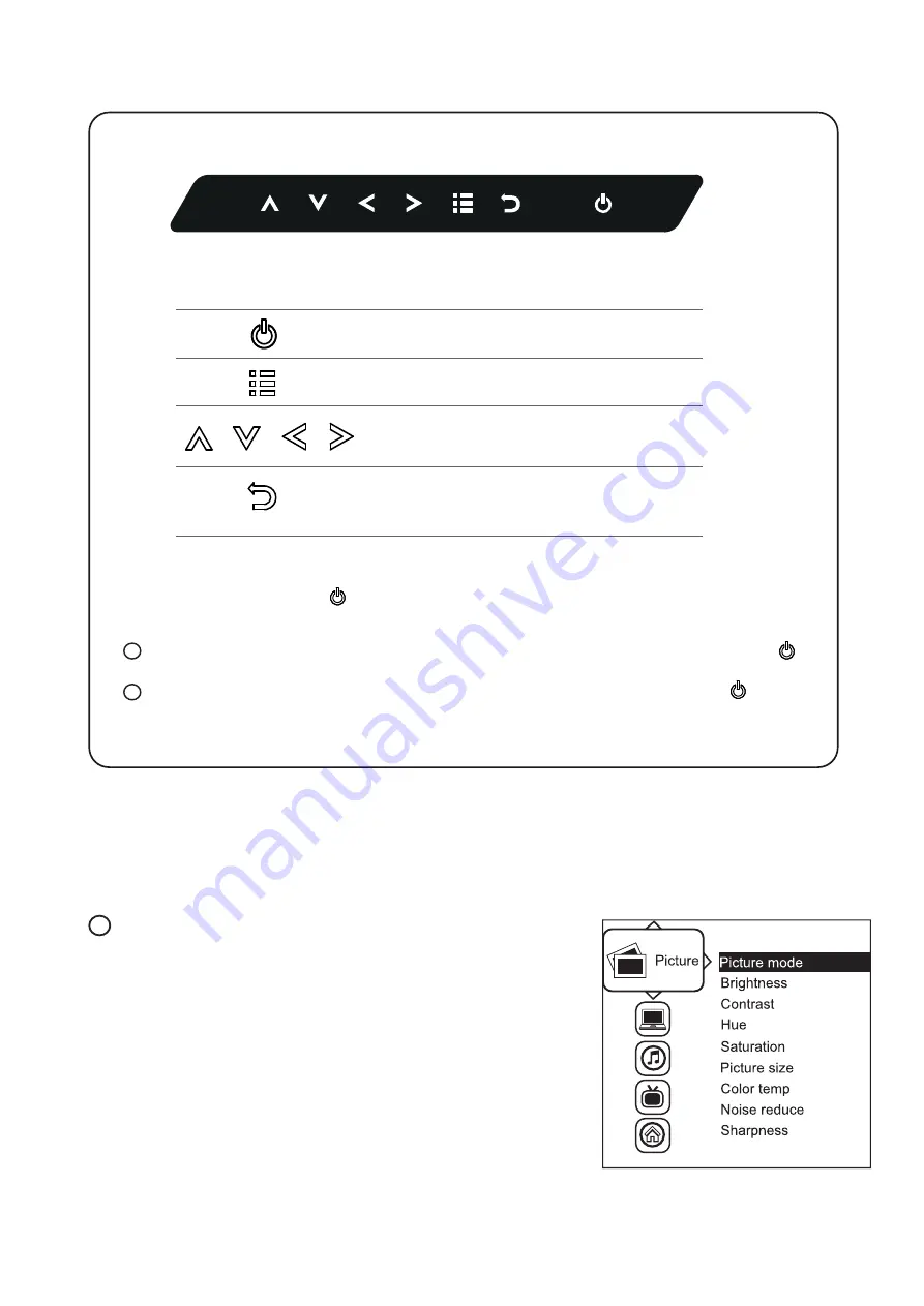
Exit the OSD screen
Go back to the previous on-screen sub-menu or 
main menu

Scroll through menu options and adjust 
the displayed control

Display the OSD menu 
Act as an Enter key to select screen setting options

Turn the monitor on or off

Membrane Switch

Function

Remark : All LED touch buttons in 

WHITE 

light. 

               The LED of 

Power        

touch button will 

fl

 ash continuously when there is no signal input.

All the LED touch buttons will automatically turn off after 10 minutes of idle status ( except the 

Power

       ).

Light up all membrane buttons, please press any button for 1 - 2 seconds ( except the 

Power

       ).

1

2

P.7

< 2.2 > On-screen Display Operation ( OSD )

 Picture 


Picture mode : 

    Standard / Vivid / Soft / User mode to choose


Brightness : 

    Adjust background black level of the screen image


Contrast :


    Adjust the difference between the image background


    (black level) and the foreground (white level)


             Hue: 


    Adjust the screen hue value


Saturation :


    Adjust the saturation of the image color


Picture size :


    Adjust the image size 


Color temp :


    Standard / Cool / Warm / User to choose 


Noise reduce :


    Reduce the noise of the image 

              Sharpness :


    Adjust the image from weak to sharp

1

RP-HF821

Summary of Contents for CyberView RP-HF821

Page 1: ...ckmount Display Panel RP HF821 Options SDI MCS AV HDMI Audio Touchscreen DC power MIL type or lockable connector User Manual Designed and manufactured by Austin Hughes dedicated KVM switch and rackmount screen technology 21 5 High Brightness FHD LCD 1000 cd m ...

Page 2: ...ervice personnel should open the chassis Opening it yourself could damage the equipment and invalidate its warranty If any part of the equipment becomes damaged or stops functioning have it checked by qualified service personnel What the warranty does not cover Any product on which the serial number has been defaced modified or removed Damage deterioration or malfunction resulting from Accident mi...

Page 3: ...esistive Capacitive 1 point touch 3 5 DC Power 24V 48V 125V 250V 3 6 MIL type or lockable connector P 11 P 12 P 13 P 14 P 15 P 16 Part 2 Specifications OSD Remote Controller 2 1 Product Specifications 2 2 On screen Display Operation OSD 2 3 Picture In Picture PIP Picture By Picture PBP P 5 6 P 7 8 P 9 10 Part 1 RP HF821 1 1 Package Content 1 2 Structure Diagram Dimension 1 3 Installation Contents ...

Page 4: ...sers not made to clean monitors and monitor screens can scratch the LCD display or strip off the finish Do not spray any kind of liquid directly onto the screen or case of your monitor Spraying liquids directly onto the screen or case can cause damage which is not covered under warranty Do not use paper towels or abrasive pads to clean your monitor Using an abrasive pad or any wood based paper pro...

Page 5: ...udio SDI USB for touchscreen DC power LCD panel LCD membrane Latch to release the display panel from the rear bracket Rear mounting bracket Power adapter basket 1 1 Package Content RP HF821 P 1 Part 1 RP HF821 unit X 1 6ft VGA cable X 1 Power adapter X 1 Power cord X 1 Fastener screw for rear bracket x 2 1 2 Structure Diagram 1 3 Front view 3 1 2 Rear view 4 2 4 Power adapter Power cord 5 5 ...

Page 6: ...ew Side View UNIT mm 1mm 0 03937 inch Bottom View Model Product Dimension W x D x H Packing Dimension W x D x H Net Weight Gross Weight 501 9 x 64 x 353 mm 19 8 x 2 5 x 13 9 585 x 124 x 557 mm 23 x 4 9 x 21 9 10 3 kg 22 7 lb 12 7 kg 27 9 lb RP HF821 1 2 Dimension P 2 ...

Page 7: ...UM CV 751 RP HF821 Q317V2 www austin hughes com Hardware and M4 4 pcs for VESA mount are not provided VESA mount 100 100mm M4 screw 1 3 VESA mount Installation P 3 RP HF821 ...

Page 8: ...crew sets are not provided Step 1 Step 2 Insert the upper part of the RP F821 display panel into the rear bracket Push the lower part of the RP F821 display panel into the rear bracket Step 3 Step 4 Fix the RP F821 display panel into the rear bracket with two fasteners Left right side Lock the RP F821 display panel by the latch on the bottom left right side latch Fastener screw ...

Page 9: ... Connectivity Digital HDMI HDMI 1 3 CEA 861 D DVI DVI D TMDS single link Analog VGA Analog 0 7Vp p Composite RCA NTSC PAL S Video 4 pin NTSC PAL Plug Play DVI VGA VESA EDID structure 1 3 Synchronization VGA Separate Composite SOG Audio Connectivity Audio Input Connector 3 5mm stereo jack Impedance Power level 30kΩ 750mV Audio Output Connector 3 5mm stereo jack Resistance Power level 30kΩ 2 8V Spea...

Page 10: ...circumstances if the user connects the LCD to PC via HDMI port for video and audio signals the LCD may display incorrectly on a full screen If so please adjust the display card setting on display size to fix the issue Environmental Conditions Operating Temperature 0 to 55 C degree Humidity 20 90 non condensing Altitude 16 000 ft Storage Non operating Temperature 20 to 60 C degree Humidity 5 90 non...

Page 11: ...lly turn off after 10 minutes of idle status except the Power Light up all membrane buttons please press any button for 1 2 seconds except the Power 1 2 P 7 2 2 On screen Display Operation OSD Picture Picture mode Standard Vivid Soft User mode to choose Brightness Adjust background black level of the screen image Contrast Adjust the difference between the image background black level and the foreg...

Page 12: ... the OSD menu is displayed English Sleep timer Set the off time PIP mode Adjust picture in picture setting PIP position Enter into PIP position PIP source Enter into the Sub source and sound source System reset Return the adjustment back to factory setting Information Select for Help 4 P 8 Audio Audio mode Movie Voice Normal Music mode to choose Volume Adjust the volume of sound Bass Set the value...

Page 13: ...enu MISC PIP Position top left top right bottom left bottom right top left top right bottom left bottom right Size Adjust the size of the Sub screen Large Small OSD Menu MISC PIP Mode Large Small LCD Monitor Large Sub screen Small Sub screen 1920 x 1200 552 x 414 480 x 360 1920 x 1080 552 x 414 480 x 360 1440 x 900 414 x 310 360 x 270 1366 x 768 392 x 294 340 x 254 1280 x 1024 368 x 276 320 x 240 ...

Page 14: ...x 508 1280 x 1024 635 x 476 2 3 2 Picture By Picture PBP 2 3 3 PIP PBP Source To select an input signal for PIP PBP Sub screen OSD Menu MISC PIP Source VGA S Video Composite DVI HDMI SDI YPbPr TV Sub Main VGA S Video Composite DVI D HDMI SDI YPbPr TV VGA x o o o o o o o S Video o x x o o o o x Composite o x x o o o o x DVI o o o x x o o o HDMI o o o x x o o o SDI o o o o o x x o YPbPr o o o o o x ...

Page 15: ...SDI 48kHz 16 20 24 bit 2 CH Synchronized Video SD SDI 48kHz 16 20 24 bit 2 CH Synchronized Asynchronized Video Compatible Video Format 3G SDI 1080p 1080p 1080i 720p 60 50Hz 4 2 2 30 25 24Hz 4 4 4 60 50Hz 4 4 4 60 50Hz 4 4 4 HD SDI 1080p 1080i 720p 30 25 24Hz 4 2 2 60 50Hz 4 2 2 60 50Hz 4 2 2 SD SDI 480i 60Hz 4 2 2 ITU R BT 656 576i 50Hz 4 2 2 Max Transmission Distance 75 ohm coaxial cable 3G SDI 1...

Page 16: ...ution to control the OSD of various CyberView LCD display up to 64 units The RS 232C is used for the communication between the PC and the first display via a 15 feet serial cable while the CAN bus is used for the various LCD displays cascade together via CAT 5 6 cable and daisy chain up to 1 000 meters Designed for use with CyberView LCD displays Austin Hughes provides a MCS input module without u...

Page 17: ...V2 www austin hughes com Built in Dual Stereo Speakers 2W x 2 3 5mm audio jacks for audio in out S Video Composite BNC AV Audio Power Audio out in in Video PC VGA DVI D HDMI S Video BNC 3 3 AV3 0 Upgrade Options RP HF821 P 13 ...

Page 18: ... link below http www austin hughes com resources driver rackmount display Step 2 Double click the Setup exe Step 3 Follow the installation instruction to finish the setup Step 4 After installation run the TouchKit program the 4 point calibration Please follow the below steps to setup the touch screen Please do the initial calibration after the first setup USB touchscreen package includes 1 x 6ft U...

Page 19: ...e 18 36V 36 75V 66 160V 180 425V Input current No load 50 mA 50 mA 35 mA 10 mA Full load 4880 mA 2442 mA 749 mA 600 mA Output rating Output voltage 12 Volt 12 Volt 12 Volt 12 Volt Output current 4 16A 4 16A 6 25A 12 5A Efficiency 85 85 91 86 3 5 Options DC Power P 15 RP HF821 1 If the unit with LCD earthing may be required For DC power option ...

Page 20: ...ckable Connector Input Part no MIL Standard MIL type Connector DC Power Male MS3470W8 33P MIL DTL 26482 VGA Male MS3470W14 15P MIL DTL 26482 Input Part no Standard Lockable Connector DC Power Male YM Ext 461CP001 D type 3W3 USB LUSB A111 00 There are several additional MIL DC and VGA connector types with varying design characteristics to meet cost considerations and to provide users with the most ...

Reviews: