background image

12

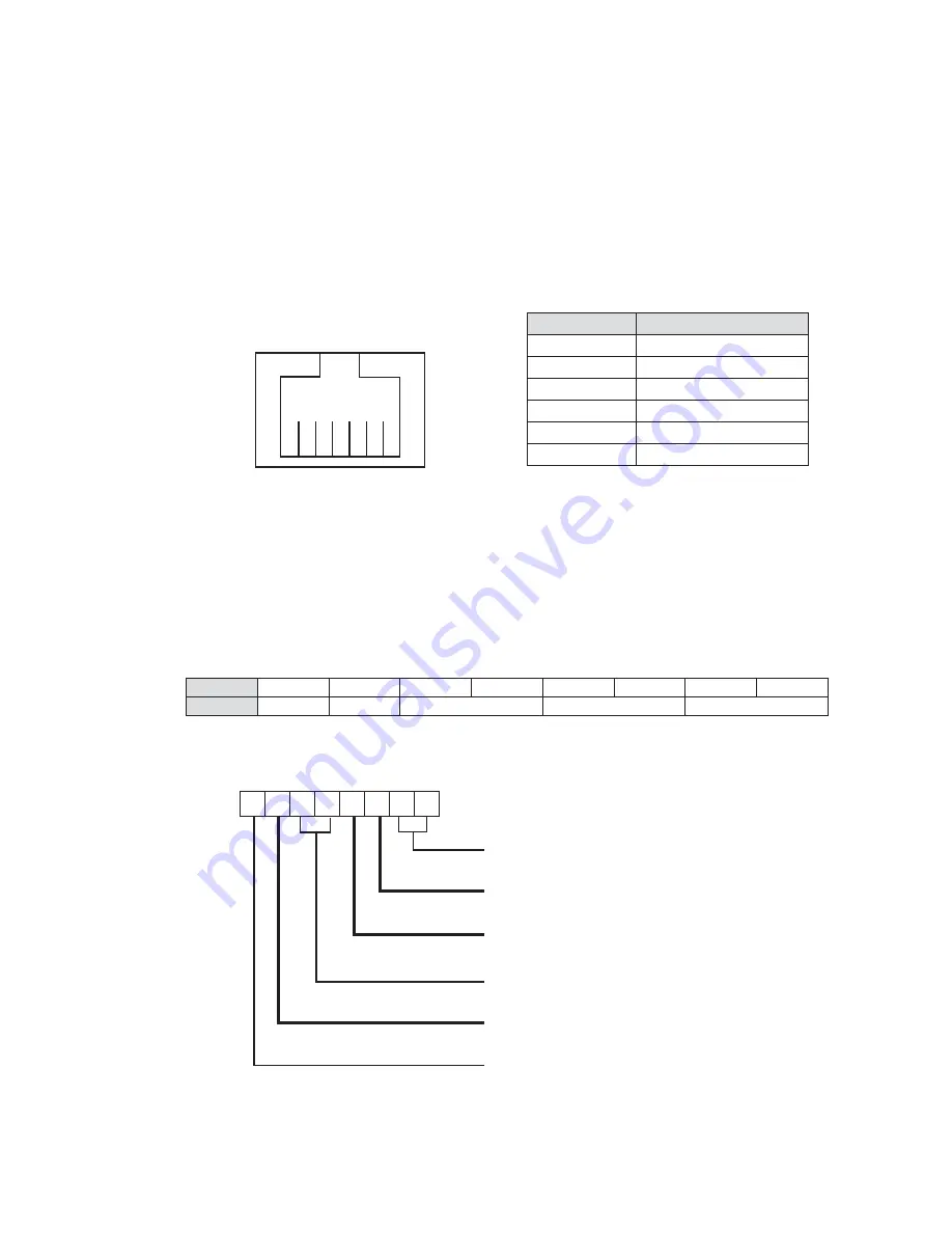
You can install a cash drawer through the cash drawer port. Please verify the pin as-
signment before installation.

Cash Drawer Pin Assignment

Pin

Signal

1

GND

2

DOUT bit0

3

DIN bit0

4

12V / 19V

5

DOUT bit1

6

GND

Cash Drawer Controller Register

The Cash Drawer Controller use one I/O addresses to control the Cash Drawer.

Register Location:

 48Ch

Attribute:

 Read / Write

Size:

 8bit

BIT

BIT7

BIT6

BIT5

BIT4

BIT3

BIT2

BIT1

BIT0

Attribute

Reserved

Read

Reserved

Write

Reserved

7 6 5 4 3 2 1 0

X


X

X


X

X

Reserved

Cash Drawer “DOUT bit0” pin output control

Cash Drawer “DOUT bit1” pin output control

Reserved

Cash Drawer “DIN bit0” pin input status

Reserved

1

6

Cash Drawer Installation

4-5. 

Summary of Contents for W-TOUCH

Page 1: ...USER MANUAL VERSION 1 0 September 2011 W TOUCH...

Page 2: ...be easily accessible and in close proximity to the machine Read these instructions carefully Save these instructions for future reference 2 Follow all warnings and instructions marked on the product 3...

Page 3: ...ing to the manufacturer s instructions Battery Caution Risk of explosion if battery is replaced by an incorrectly type Dispose of used battery according to the local disposal instructions Safety Cauti...

Page 4: ...ction recycling and disposal procedure To prevent possible harm to the environment or human health from uncontrolled waste disposal please separate this from other types of wastes and recycle it respo...

Page 5: ...v Revision History Changes to the original user manual are listed below Revision Description Date 1 0 Initial release 2011 September...

Page 6: ...3 2 3 I O Ports View 4 2 4 System Dimension 4 3 System Assembly Disassembly5 3 1 Open Cable Cover 5 3 2 Open the System 5 3 3 HDD Replacement 6 3 4 RAM Replacement 7 4 Peripheral Installation 8 4 1 MS...

Page 7: ...vii 5 Speci cations 14 6 Jumper Setting 15 6 1 C48 Motherboard 15 6 1 1 Motherboard Layout 15 6 1 2 Connectors Functions 17 6 1 3 Jumper BIOS Utility Setting 18 Appendix Drivers Installation 25...

Page 8: ...viii The page is intentionally left blank...

Page 9: ...1 Packing List 1 Standard Accessories 1 1 System a Power adapter b Power cord c VGA cable d RJ45 DB9 cable x2 e Wall mount kit f a b c d e f...

Page 10: ...2 Optional Accessories 1 2 MSR module a SSD card b Fingerprint module c iButton module d a b c d...

Page 11: ...View 2 Front Side View 2 1 Item No Description 1 Touch screen 2 MSR module optional 3 Fingerprint or iButton module optional Rear View with Stand 2 2 Item No Description 4 Safety label 5 Cable cover 1...

Page 12: ...m Dimension 2 4 a b c d e f g h i j k Item No Description a DC IN b LAN c Cash drawer d MIC in e Line out f COM port 1 2 3 4 from left to right g USB x4 h Parallel i 2nd power button j VGA k HDD slot...

Page 13: ...ver Open the System 3 2 To open the system please open the cable cover rstly as steps dscribed in chapter 3 1 1 Loosen the hex socket cap screws M3x10 to open the rear rear cover of the system Note If...

Page 14: ...em off Find the HDD located at the right side 2 Pull the HDD tray from the system For easier removal pull the plastic sheet see picture at the same time 3 Attach the HDD to the HDD tray and slide it i...

Page 15: ...bed in chapter 3 2 Removing a RAM module 1 Find the memory slot at the right side of the motherboard 2 Flip the ejector clips outwards to remove the memory module from the memory slot Installing a RAM...

Page 16: ...ore the installation please open the cable cover rstly as steps described in chapter 3 2 1 Insert MSR module in place and fasten the screws M3x2 on the back to secure the module 2 Connect MSR cable to...

Page 17: ...side of the system Choose one side and follow the steps below Before the installation please open the cable cover rstly as steps described in chapter 3 1 2 Connect the iButton cable to the RJ45 COM p...

Page 18: ...for installation 2 Attach the metal bracket to the back side of the sytem by fastening the screw x1 as picture shown 3 Align the large end of the teardrop mounting holes x4 on the wall plate with the...

Page 19: ...Find the two positioning pins on the system 1 Insert the SSD card to the cable connector as shown by arrow 2 Align the SSD card to the positioning pins and fasten the screws x2 as picture shown 4 Fas...

Page 20: ...egister The Cash Drawer Controller use one I O addresses to control the Cash Drawer Register Location 48Ch Attribute Read Write Size 8bit BIT BIT7 BIT6 BIT5 BIT4 BIT3 BIT2 BIT1 BIT0 Attribute Reserved...

Page 21: ...Bit 1 Reserved Bit 0 Reserved Note Please follow the Cash Drawer control signal design to control the Cash Drawer Cash Drawer Control Command Example Use Debug EXE program under DOS or Windows98 Comma...

Page 22: ...e Cash Drawer Port 1 x RJ 11 12V 24V Audio Jack 1 x Line out 1 x Mic in Power Power Adapter 19V 90W Control Indicator Power Button 1 Peripheral MSR 3 Tracks MSR USB Fingerprint Fingerprint USB iButton...

Page 23: ...15 14 13 12 11 10 9 8 7 6 5 4 3 2 1 15 17 18 16 2 11 DDR3_A1 CN24 MINI_PCIE RJ45_2 PWR1 RJ11_1 CN18 CN14 RJ45_1 JP5 JP4 JP18 CN23 USB2 USB1 CN29 JP19 CN21 CN16 CN17 SKT1 JP8 JP1 FAN_CPU1 CN4 CN3 CN1 C...

Page 24: ...16 DDR3_A2 C48 V2 1 BOTTOM LAYER...

Page 25: ...6 LVDS CN27 Inverter Connector CN29 System Fan DDR3_A1 DDR3 SO DIMM1 DDR3_A2 DDR3 SO DIMM2 PRN1 Parallel Port PWR1 19V DC Jack RJ11_1 Cash Drawer Connector RJ45_1 COM1 COM2 COM3 COM4 RJ45_2 LAN SATA1...

Page 26: ...tage can be set to 5V or 12V by setting jumper JP18 on the motherboard When enabled the power is available on pin 10 of the RJ45 serial connector If you use the serial RJ45 to DB9 adapter cable the po...

Page 27: ...4 12V 8 5 7 2 1 3 6 4 COM4 5V 8 5 7 2 1 3 6 4 12V 8 5 7 2 1 3 6 4 Function JP1 CMOS Normal 2 1 CMOS Reset 2 1 Manufacturer Default Setting 4 To switch on the power select Power Please save the change...

Page 28: ...1 3 4 12V 2 1 3 4 Power Mode Setting Function JP9 ATX Power 2 1 AT Power 2 1 System Indicator Function JP10 Disable 8 5 7 2 1 3 6 4 Enable 8 5 7 2 1 3 6 4 Inverter Selection Function JP14 CCFL LED Man...

Page 29: ...low 3 Connect the power cable to the system and power on the system in ATX mode press the power button and it will fail power on in AT mode turn on system power 4 Remove the power cable from the syste...

Page 30: ...800 x 600 18 Single 8 5 7 2 1 3 6 4 800 x 600 18 Single 8 5 7 2 1 3 6 4 1024 x 768 18 Single 8 5 7 2 1 3 6 4 1280 x 1024 24 Dual 1st VGA port 8 5 7 2 1 3 6 4 remark specialized for Sharp 12 1 LQ121S1L...

Page 31: ...otherboard jumper setting 1 Power on the system and press the DEL key when the system is booting up to enter the BIOS Setup utility 2 Select the Advanced tab 3 Select Power Con guration COM VGA Ports...

Page 32: ...ght click Desktop Find Graphics Properties and enter the manu 2 Make sure the Display Device is same as follows No Output Interface Connector Jumper Intel Graphics Driver Device Name 1st LCD Panel CN2...

Page 33: ...d the most recent drivers and utilities and obtain advice regarding the installation of your equipment please visit the AURES Technical Support Website www aures support fr French www aures support fr...

Reviews: