


58
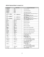
Command
Code (hex)
Function Description
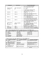
ESC W s x1 x2 y
1B 57 s x1 x2 y
Set or cancel the window range at horizontal
scroll mode
�
1
≦
x1
≦
x2
≦
14h, for columns
location.
�
y = 1~2, for lines location.
�
s = 0: cancel
s = 1: set
CLR
0C
Clear display screen, and clear string mode
CAN
18
Clear cursor line, and clear string mode
ESC * n
1B 2A n
Brightness adjustment
�
n = 1
~
4, n = 4 for highest brightness
US X n
1F 58 n
ESC _ n
1B 5F n
Set cursor on/off
�
n = 1: cursor on
n = 0: cursor off
ESC f n
1B 66 n
Select international Character
�
About n, refer.
*3
ESC c n
1B 63 n
Select character code table
�
About n, refer.
*4
ESC = n
1B 3D n
Select peripheral device, display or printer
�
n='1': enable printer only
n='2': enable display only
n='3': enable both of printer and display
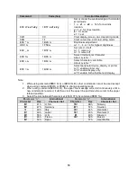
Note:
1. While using command
Ŗ
ESC Q A
ŗ
or
Ŗ
ESC Q B
ŗ
, other commands cannot be used except
when using command
Ŗ
CLR
ŗ
or
Ŗ
CAN
ŗ
to change operating mode.
2. When using command
Ŗ
ESC Q D
ŗ
, the upper line message will scroll continuously until a
new command is received, it will then clear the upper line and move the cursor to the upper
left-end position.
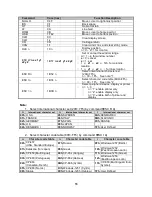
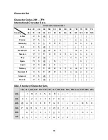
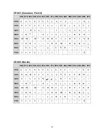
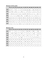
3. Select the international Character set (20h
Ŕ
7Fh) by command
Ŗ
ESC f n
ŗ
.
Parameter “ n”
International
Character Set
Parameter “ n”
International
Character Set
Character
Hex
Character
Hex
Ř
A
ř
41h
U.S.A.
Ř
N
ř
4Eh
Norway
Ř
G
ř
47h
Germany
Ř
W
ř
57h
Sweden
ř
I
ř
49h
Italy
Ř
D
ř
44h
Denmark I
Ř
J
ř
4Ah
Japan
Ř
E
ř
45h
Denmark II
Ř
U
ř
55h
U.K.
Ř
L
ř
4Ch
Slavonic
Ř
F
ř
46h
France
Ř
R
ř
52h
Russia
Ř
S
ř
53h
Spain
1Fh
User-Define
Summary of Contents for Odysse II
Page 1: ...User Manual February 2011 Revision 1 0 ...
Page 8: ...8 e Biometric Reader fingerprint f Customer Display VFD g 2nd Display ...
Page 9: ...9 2 System View 2 1 Front Side view 2 2 Rear view ...
Page 10: ...10 2 3 I O view ...
Page 32: ...32 6 Jumper Settings 6 1 Main Board Layout ...
Page 36: ...36 6 3 Connectors Location ...
Page 44: ...44 Appendix B Dimensional Drawings All dimensions in mm ...
Page 45: ...45 ...


