background image

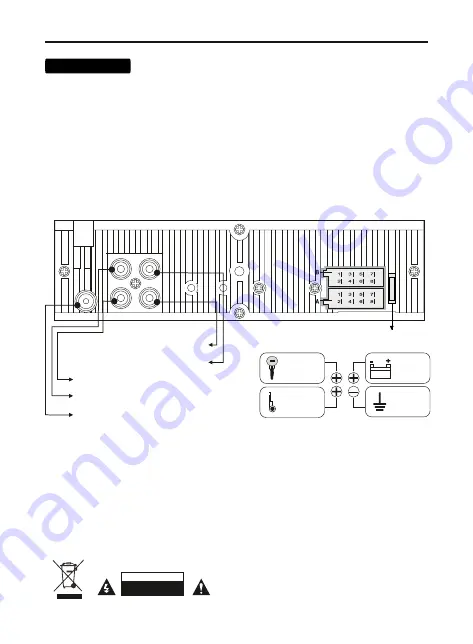
4. Connect the red wire 

(A7)

 to the ACC terminal of the ignition switch.

Note:

 every time the yellow wire is disconnected from the 12 volt power circuit or the battery 

terminal is removed, the device will revert to the factory settings.

7. Connect the orange wire 

(A6)

 to the circuit where +12 volts appears when the dimensions 

are turned on.

1. Make sure that the on-board voltage of your vehicle is +12 volts

3. Connect the yellow 

(A4)

 wire to the +12 Volt DC power circuit.

2. Remove the fuse from the device before connecting the wires.

5. Connect the black wire 

(A8)

 to the metal part of the car body.

6. Blue wire 

(A5)

 - Connect to the amplifier's remote turn-on input or the antenna motor 

control input.

8. Connect the rest of the wires according to the diagram.

Back speakers

B2

 Right channel – (purple-black)

B6

 Left channel – (white-black)

B3

 Right c (grey)

B4 

Right channel – (grey-black)

B5

 Left c (white)

B8

 Left channel – (green-black

)

Front speakers

B7

 Left c (green)

B1

 Right c (purple)

ATTENTION

DO NOT OPEN

5

Connection

Antenna connection input
radio receiver

RCA front – Left (white)

RCA back – Right (red)

RCA back – Left (white)

RCA front – Right (red)

10 A

fuse

A4


B 12V DC

A8

 Minus (ground) - connect to a metal part

A6 

Dimmer. Connection to vehicle lighting control.

+12 VDC - connect to the remote turn-on input of the amplifier or 
the antenna motor control input (no more than 100 mA, 12 V).

A7

 ACC + 12V DC wire - Connect to a power source that can be 

turned on and off from the vehicle's ignition switch.

car body or connect to the negative terminal of the battery.

A5

 + 12V control wire to control the motorized antenna and 

remotely turn on / off amplifiers or other active auxiliary devices.

RED
ACC +12V

YELLOW

constant

power

+12V

BLACK

ground

MINUS

BLUE

control

wire

+12V

Summary of Contents for AMH-440BT

Page 1: ...WARNING PLEASE READ CAREFULLY BEFORE USING OWNER S MANUAL USB RECEIVER AMH 440BT AMH 450BT...

Page 2: ...cturer does not accept any responsibility for the use of this manual and decisions based on its use In order to improve product quality product specifications and features are subject to change withou...

Page 3: ...ent Precautions Package bundle and installation Connection Appearance control elements Overall size Remote control Main functions Radio USB Bluetooth Phone app Technical features 3 4 5 6 7 7 9 9 10 11...

Page 4: ...or any loss of data caused by device damage repairs or any other reason 5 Do not disassemble the device yourself This may void the warranty 6 Do not use alcohol solvents or gasoline for cleaning plast...

Page 5: ...check the functionality of the system before fixing it in the mounting box 5 Insert the device into the mounting cover and slide it inward until it clicks into place 1 Install the mounting cover into...

Page 6: ...purple black B6 Left channel white black B3 Right channel grey B4 Right channel grey black B5 Left channel white B8 Left channel green black Front speakers B7 Left channel green B1 Right channel purp...

Page 7: ...utton 7 Liquid crystal display 8 Button for selecting radio frequency range autosearch of stations Bnd Ams 9 Button for fast reverse playback select the previous track hang up the handset 10 Preset bu...

Page 8: ...1 When the lithium battery has lost its capacity replace it as shown in the illustration 2 Press and hold the latch in direction indicated by arrow 1 Pull the holder at the same time from the remote c...

Page 9: ...ed battery can damage the remote control Keep batteries out of the reach of children Remote control 1 Turn on off the device 2 Source selection 3 Muting the sound Mute 4 Radio preset buttons 5 Track s...

Page 10: ...he front panel to select sound adjustment options The parameters are selected in the following sequence Volume BASS bass TRE treble BAL left and right balance FAD front and rear balance EQ equalizer s...

Page 11: ...g mode Press the button 9 or 2 to change the frequency step by step Hold the button 9 or 2 to change the frequency step by step Automatic station search Press the button 9 or 2 to quickly search for s...

Page 12: ...r authorization 1234 3 In case of successful connection the BT indicator on the display of the receiver will stop blinking and light up constantly 4 The audio signal from the mobile device music and c...

Page 13: ...ttings are available in the AurA mobile application for Android or IOS 1 Install the AurA app from Google Play or App Store 2 Connect your smartphone to the receiver via Bluetooth 3 Launch the AurA ap...

Page 14: ...mm 2 4 HHz Antenna impedance AUX IN Audio input level Jack Frequency Radio FM Preset memory for radio stations Received frequency range FM Speaker Impedance Frequency Response Range Display viewing a...

Page 15: ...Seller name stamp Model name Serial No Buyer name Buyer address Phone No Sales date Signature WARRANTY CARD 14...

Page 16: ...if it has the following features 1 The fact that water or other liquids have entered the amplifier 2 Incorrectly filled in warranty card or its absence 3 Unqualified installation connection of the pro...

Page 17: ...16...

Page 18: ...www aurael ru 2021 AURA Electronics Inc All rights reserved Note Technical data is subject to change without prior notify...

Reviews: