background image

Page


20

DZONE88

 - Digital array, 8 inputs 8 outputs

English

6-17  Device management

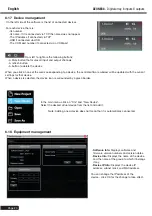
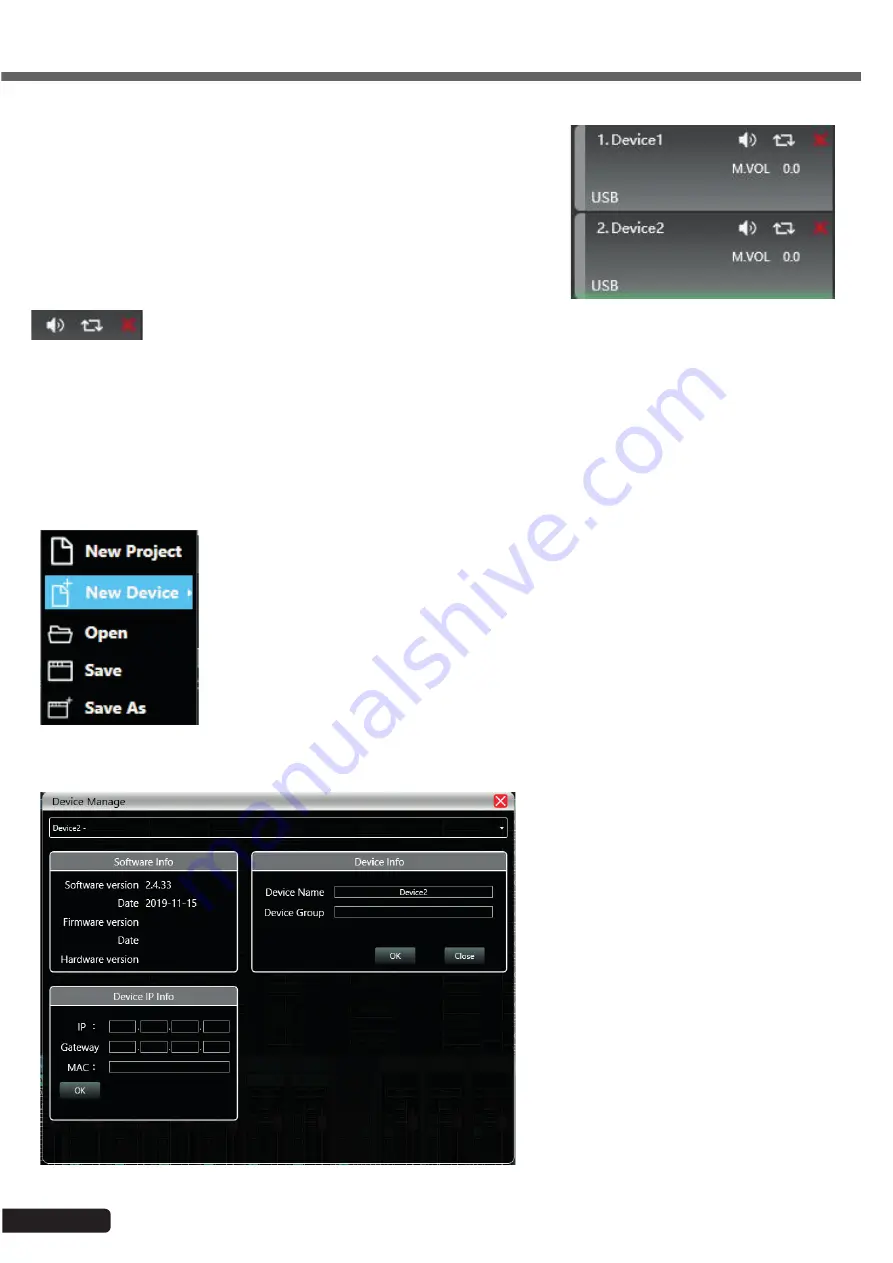
On the left side of the software is the list of connected devices.

For each device, there is:


-Its number.


-Its name. If it is connected via TCP, the name does not appear.


-The IP address if connected via TCP


-USB if connected via USB


-The COM port number if connected via a COM port

 From left to right are the following buttons:


-A Mute button that mutes all input and output channels


-A refresh button


-A button to delete the device

When you click on one of the areas corresponding to a device, the central software window will be updated with the current 
settings for that device.
When a device is selected, the device icon is surrounded by a green border.

In the main menu, click on "File" and "New Device".
Select the desired virtual device from the list and add it.

Note: Adding a new device does not mean that it is automatically connected.

6-18  Equipment management


-

Software Info:

 Displays software and 

firmware version numbers and version dates.


-

Device Info:

 Displays the name of the device 

and the name of the group to which it belongs 
if any.


-

Device IP Info:

 Displays the device IP 

address, subnet mask and MAC address.

You can change the IP address of the 
device - click OK for the change to take effect.

Summary of Contents for H11041

Page 1: ...8x8 DIGITAL MATRIX DZONE POWER NET LINK INPUT A B C D E F G H 1 2 3 4 5 6 7 8 48V OUTPUT P U S H E N T E R SELECT ESC ETHERNET AC 100 240V 50 60Hz GPIO RS 485 RS 232 RX V 1 2 3 5 4 6 7 8 G TX G 8 7 6 5 4 3 2 1 OUTPUT INPUT H G F E D C B A ...

Page 2: ...use a fire or electric shock Never spill liquids of any kind on the product 15 Damage requiring maintenance Refer all servicing to qualified service personnel in the following cases When the power cord or plug is damaged If liquid has been spilled or objects have fallen into the product If the product has been in contact with rain or water If the product does not operate normally by following the ...

Page 3: ...io specifications Frequency response Line 20Hz 20kHz 0 5dB Mic 20Hz 20kHz 1 5dB Total harmonic distortion Line 90dB 12dBu 1kHz A weighted Mic 86dB 7dBu 1kHz A weighted Signal to noise ratio Line 105dB 12dBu 1kHz A weighted Mic 95dB 7dBu 1kHz A weighted Connector and indicators USB Micro B type driverless TCP IP RJ 45 RS232 Serial communication port RS485 Serial communication port LED indicators Po...

Page 4: ...C B A Power button Fuse Power input RJ45 port RS485 port Outputs Inputs RS232 port GPIO 8x8 DIGITAL MATRIX DZONE POWER NET LINK INPUT A B C D E F G H 1 2 3 4 5 6 7 8 48V OUTPUT PUSH ENTE R SELECT ESC LCD display Return button USB B port Navigation wheel Phantom power indicators Output indicators Computer connection indicator Power indicator Dante connection indicator unused Input indicators ...

Page 5: ...ting saved presets The presets that you have saved via the software can be accessed directly from this menu A C LINE LINE B D LINE MIC 5DB MENU 4 INPUT SOURCE Menu 4 Setting the type of each input Each input can be either line level or mic level For mic level inputs you can set the level in 5 dB steps IP 192 168 111 199 GATE 0 0 0 0 OK MENU 5 IP SET Menu 5 Setting the IP address and subnet mask DZ...

Page 6: ...ent for recalling or resetting the various applications 5 2 Operating system environment and installation The software is compatible with Windows 7 Windows 8 and Windows 10 operating systems on which NET Framework 4 0 is installed NET Framework NET 4 0 is available for download from the Microsoft website The software does not require any particular installation Unpack the archive in a directory of...

Page 7: ...Page 7 DZONE88 Digital array 8 inputs 8 outputs English 5 3 Interface overview Software main page Once connected to the array the software looks like this ...

Page 8: ... 9 List of inputs and outputs 5 3 1 List of menus New Project Create a new project New Device Add a new array Open Open an existing project Save Save the current project Save As Save the current project under a different name Device menu Device Manage the names IP addresses etc of connected arrays Channels Rename the input and output channels Channel Copy Copy parametres from one or more channels ...

Page 9: ...reset as a startup preset Preset Lock Lock a preset with a password Preset UnLock Unlock a preset Import Preset Import a preset from the computer Export Preset Save a preset to the computer Import Package Import a group of presets from the computer Export Package Save a group of presets to the computer System menu Language Select the language of the interface About Provides information on internal...

Page 10: ...l have to be performed Setting Choose the ports on which the detection operations take place Opposite is the port configuration window Click Refresh to update the port list Link Create groups of arrays in order to control several parameters on several arrays at the same time 5 3 3 Device list After scanning or manually adding arrays all the connected arrays will appear in this list ...

Page 11: ...ttings Delay settings Limiter settings Mastering settings Anti feedback settings Parametric equaliser settings Parametric equaliser settings Auto mix settings Double click on each of these buttons to open the corresponding module The blue buttons correspond to the inputs the green buttons correspond to the outputs You can open several modules at the same time 5 3 5 DSP module access buttons Each w...

Page 12: ...rface Double click on the button The input interface is used to Set the polarity Mute the channel Mute Select the type of input Line microphone or test signal The test signal is sent to two channels at the same time When the channel is on microphone level phantom power can be enabled and the gain setting ranges from 0 to 40dB 6 2 Test interface In the input setting interface click on Setting The g...

Page 13: ...tton The feedback reducer has two levels Level 1 and Level 2 Level 2 is more powerful than level 1 6 4 Noise Gate setting interface Double click on the button 6 5 Input equalisation Double click on the button You can enlarge the window by clicking on the button allowing for better accuracy 6 5 1 Function buttons ...

Page 14: ...ngs Copy Copies the current settings to apply them to another channel Paste Applies the settings copied using the Copy button Reset Applies the default values of the equaliser 6 5 2 Multiple views 6 5 3 Graphic equalisation Move the equalisation points to the desired setting 6 5 4 Equalisation by value Each equalisation point can be selected using the buttons below the graph Each button shows the ...

Page 15: ...requency on which they act and the value of the slope 6 5 6 Equalisation presets This window allows you to save an equalisation preset on the computer retrieve one from the computer delete or rename it 6 6 Input compressor Double click on the button The window opposite shows the available settings for the input compressor When the function is active you can graphically move the curve to modify the...

Page 16: ...vel ranging from 60dB to 12dB 6 8 Array Double click on the button The top row represents the inputs and the left column represents the outputs Each input can be assigned to one or more outputs To assign an input to an output double click on the box corresponding to the desired connection For each connection you can specify the gain level using either the slider on the right or the input field The...

Page 17: ...yed in feet ft cm or milliseconds ms To enable the delay on an output channel click on the red button to change it to green The circular arrow resets the delay to zero 6 11 Output compressor Double click on the button This section works like the compressor section described in paragraph 5 6 6 12 Output limiter Double click on the button The window opposite shows the settings available for the limi...

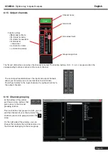
Page 18: ...nput channels Each input channel is broken down as follows Channel name Gain in dB Gain adjustment Group assignation Input type Line or mic Function status M stands for Mute stands for polarity A stands for anti feedback N stands for gate E stands for equaliser C stands for compressor The Mute M button is red when the channel is muted The function buttons A N E et C are green when the correspondin...

Page 19: ...e current channel The central part located between the input and output channels allows you to assign one or more functions to all channels The left part relates to the input channels the right part relates to the output channels 6 16 Channel grouping At the bottom of the central part there are two buttons that give access to the channel grouping function This function has four groups in which you...

Page 20: ...areas corresponding to a device the central software window will be updated with the current settings for that device When a device is selected the device icon is surrounded by a green border In the main menu click on File and New Device Select the desired virtual device from the list and add it Note Adding a new device does not mean that it is automatically connected 6 18 Equipment management Sof...

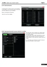
Page 21: ... OK to save the changes 6 20 Copying channels from one device to another In the main menu click on Device and Channel Copy In this window you can copy the channel status from one device to another On the left side you can select the channels you want to copy and the channels you want to copy them to On the right side you can select the functions you want to copy You cannot copy input channels to o...

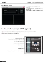
Page 22: ...lows for remote control of the main functions of the DZONE88 Equipped with a touch screen it allows basic operations to be carried out remotely It is connected to the DZONE88 via the RS485 port Access to the main screen Access to the first 6 presets and general volume Access to input channel levels Access to output channel levels Access to 2 presets Language selection Firmware and internal softwar...

Page 23: ... 8 ZONE 5 ZONE 7 ZONE 1 ZONE 3 ZONE 2 ZONE 4 WEBRADIO 1 MPU130T 100V RS485 GPIO ETHERNET AC 100 240V 50 60Hz GPIO RS 485 RS 232 RX V 1 2 3 5 4 6 7 8 G TX G 8 7 6 5 4 3 2 1 OUTPUT INPUT H G F E D C B A DZONE88 2 SALLE 1 In Gain Out Gain Preset Language DeviceInfo MainGain Preset M 100 Main 1 2 3 4 5 6 8 Block diagram ...

Page 24: ...tion For this reason the technical characteristics and physical configuration of the products may differ from the specifications and illustrations presented in this manual For the latest information and updates on AUDIOPHONY products log on to www audiophony com AUDIOPHONY is a registered trademark of HITMUSIC SAS P A Cahors Sud 46230 FONTANES FRANCE ...

Reviews: