background image

Continuous Sealer

D 552 AVT

Maintenance

33

7.6  Replacing the heating elements

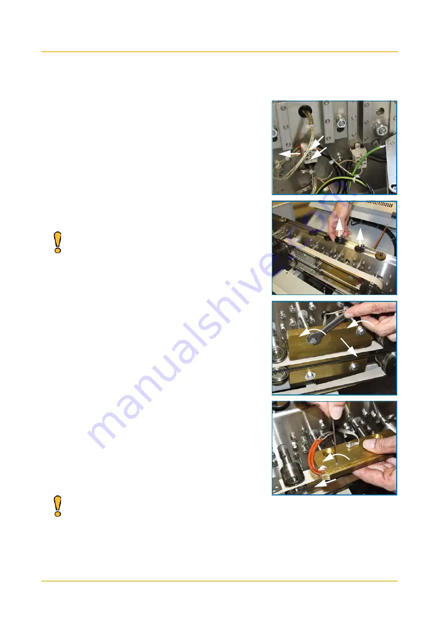
Replace the heating elements as follows:

1. Loosen the clamping screws in the

connecting block.

2. Pull the wires from the connecting

block.

3. Cut through the cable binders.

4. Put the heating block in the uppermost

position.

Pull the lifting pin up and turn the

lifting plate in such a way that it

appears over the edge of the

protective cover.

5. Loosen the mounting bolts.
6. Take the heating block from the machine.

7. Loosen the Allen bolt at the back of the

heating block.

8. Take the heating element from the heat-

ing block.

9. Place a new heating element.

10. Carefully  tighten the Allen bolt at the

back of the heating block.

Do not tighten the Allen bolt too

much, or the heating element may

get damaged.

Summary of Contents for D 552 AVT

Page 1: ...Continuous Sealer D 552 AVT D 552 AVT ENG Rev 01 User manual www audion com...

Page 2: ...2...

Page 3: ...ot liable for any damage caused by specifications deviating from the standard version Although this operating manual was compiled with the utmost care Audion Elektro BV does not accept any liability f...

Page 4: ...ption in 1947 Audion has gained a lot of experience and expertise with a wide variety of sealing and packaging machines Our solutions for packaging problems are unique Our many years of experience tog...

Page 5: ...er 13 3 2 Placing the sealer 13 3 3 Connecting the sealer 14 3 4 Adjusting the sealer 15 3 4 1 Adjusting the height of the sealing unit 15 3 4 2 Adjusting the horizontal position of the conveyor belt...

Page 6: ...ating elements 33 7 7 Adjusting the pressing force of the heating blocks 35 7 8 Adjusting the pressing force of the press rollers 35 7 9 Adjusting the pressing force of the cooling plates 36 7 10 Adju...

Page 7: ...n EC mark This means that the sealer meets the fundamental health and safety requirements of the European Communities Audion Elektro BV Hogeweyselaan 235 1382 JL Weesp The Netherlands Telephone 31 0 2...

Page 8: ...on the delivered product Any parts we replace in order to meet our warranty obligations become our property Should the other party not meet obligations resulting from the agreement entered into betwee...

Page 9: ...following symbols are used in this user manual A tip on how a task can be carried out more efficiently Instructions for carrying out a task in the correct manner Danger of injury to the user or damag...

Page 10: ...r manual Failure to observe the safety instructions may cause unacceptable risks The operating personnel must be familiar with all chapters of this user manual with the exception of Installation and M...

Page 11: ...pany such as safety shoes gloves and goggles Use the PPE required on the shop floor such as safety shoes gloves and goggles and or hearing protection in particular when carrying out maintenance work C...

Page 12: ...live Should the sealer catch fire never use water to extinguish the fire Because the machine is live this may result in life threatening situations During use you are obliged to have a fire extinguish...

Page 13: ...al metal parts and the earth 3 Fuse in 230 V circuit If the voltage gets too high the fuse will blow cutting off the power sup ply 4 Emergency stop button In case of a hazard this will immediately and...

Page 14: ...es present Sealer User manual The sealer is packaged in environmentally friendly material that can be disposed of as ordinary household waste Keep the crate and the packaging material so the sealer ca...

Page 15: ...Installation 14 3 3 Connecting the sealer 1 Check whether the main switch is in the 0 position 2 Put the plug in the socket...

Page 16: ...nveyor belt is adjusted as follows 3 4 2 Adjusting the horizontal position of the conveyor belt The horizontal distance of the conveyor belt in relation to the sealing unit is adjusted as follows 1 Se...

Page 17: ...belt brackets 2 Take the conveyor belt from the frame Always make sure two people lift the conveyor belt from the frame together 3 Position the conveyor belt on the frame at the desired height The hei...

Page 18: ...g of ready to use bags made of polyethylene PE polypropylene PP thin PVC and various laminates with a thickness of between 20 m and 150 m Do not use the Continuous Sealer for any other applications Th...

Page 19: ...accessible The conveyor belt will transport the bags to be sealed along the heating blocks the press rollers the cooling plates and the after press rollers that are positioned inside the housing The h...

Page 20: ...he sealing speed Sync synchronising the sealing speed and the speed of the conveyor belt 3 Up down Press to increase or reduce a setting 4 Emergency stop button In case of a hazard this will immediate...

Page 21: ...necessary put the plug in the socket 2 If necessary turn the EMERGENCY STOP BUTTON clockwise to reset it 1 Press the PROG button until the TEMP led is on 2 Press the ARROW keys to increase or reduce t...

Page 22: ...set temperature deviates more than 5 C from the actual sealing temperature Make a number of trial seals and if necessary readjust the sealing temperature and speed 1 Press the HEAT button 2 Press the...

Page 23: ...2 Wait until the TEMP led is no longer blink ing The sealer has now reached the set temperature and is ready for sealing 1 Position the bags on the conveyor belt and guide the bag into the infeed gui...

Page 24: ...ature is over 80 C the sealer will first switch to COOLRUN mode The heating is switched off and the blower and the motor will continue to run until the sealing temperature has dropped to below 80 C Th...

Page 25: ...In case of emergency situations always make use of the EMERGENCY STOP BUTTON immediately Do not use the EMERGENCY STOP BUTTON to switch off the sealer in normal circumstances Make sure the cause of th...

Page 26: ...operly in the socket The power supply is out of order Check the power supply The emergency stop button has been pressed Reset the emergency stop button Internal malfunction Contact your dealer or Audi...

Page 27: ...s incorrect Check the frequency of the grid and set the PCB jumpers correctly Error code E2 Loose wire in the tem perature sensor PT100 Check the connection of the wiring of the tem perature sensor PT...

Page 28: ...arrying out any maintenance work Do not use any water abrasive cleaning agents chemical solvents or other liquids when cleaning the machine The maintenance schedule is based on normal use The frequenc...

Page 29: ...personnel see the preface Part Work PTFE belts Make sure the PTFE belts are clean If necessary clean with a damp cloth Heating blocks Make sure the heating blocks are clean If necessary clean with a...

Page 30: ...t Never carry out maintenance on the Continuous Sealer while it is live 3 Loosen the two locking handles at the sides a few turns 4 Tilt the housing so that the sealing slit is at the front 5 Tighten...

Page 31: ...and turn the lifting plate in such a way that it appears over the edge of the protective cover 2 Push the two tension rollers inward until they are locked While pushing the tension roller inward the...

Page 32: ...moothly across the rollers 6 Place the V belts back across the pullies Make sure the V belts run smoothly across the rollers with the serrated edge on the outside 7 Put the cooling plates the after pr...

Page 33: ...he serrated edge on the outside 1 Loosen the nut at the back of the shaft one turn Do not loosen the nut completely otherwise the tension roller will not remain suspended 2 Slide the tension roller to...

Page 34: ...t position Pull the lifting pin up and turn the lifting plate in such a way that it appears over the edge of the protective cover 5 Loosen the mounting bolts 6 Take the heating block from the machine...

Page 35: ...ghtening of the mounting bolts 14 Push the connecting wires back into the connecting block Take care to connect the wires in the correct position 15 Tighten the screws in the connecting block again 16...

Page 36: ...Note that the adjustment depends on the position horizontal or vertical of the housing 1 Turn the setting nut to adjust the pressing force Try to keep the pressing force down as far as possible so as...

Page 37: ...nt depends on the position horizontal or vertical of the housing 1 Turn the setting nut to adjust the pressing force Try to keep the pressing force down as far as possible so as to minimise wear and t...

Page 38: ...the two locking nuts at the bottom of the conveyor belt a few turns 2 Turn the tightening bolts to adjust the pressing force Turn to the right to increase the tension in the conveyor belt to the left...

Page 39: ...n applied as it is disposed of is to be collected separately from the other waste and may not be discarded together with residual waste 8 2 Correct disposal for reuse The machine or piece of equipment...

Page 40: ...Continuous Sealer D 552 AVT Technical information 39 Appendix 1 Technical information A1 1 Dimensional drawing Figure 8 1 Dimensional drawing R R R R N N N N S S S S R R R R F F F F RR k...

Page 41: ...ax 10 metres per minute IP value IP20 Electricity Voltage 230 V 16 A Frequency 50 60 Hz Earthing earthed Power 1100 W Deviation from mains power system 10 Fuse 4 AT Length of power cord 1 8 m Film Min...

Page 42: ...am 41 Appendix 2 Electrical Diagram Maintenance to the electrical installation may only be performed by authorised maintenance personnel Always remove the plug from the socket before carrying out main...

Page 43: ...Electrical Diagram 42...

Page 44: ...Continuous Sealer D 552 AVT Electrical Diagram 43...

Page 45: ...ended consumables in stock so that a defective part can be replaced quickly and the production process resumed without delay A3 1 Consumables Part Qty per machine Article number V belt large 2 685216...

Page 46: ...iews 9 1 9 1 9 1 9 9 9 9 2 2 2 2 9 9 9 9 4 4 4 4 3 3 3 3 1 1 1 1 0 0 0 0 9 9 9 9 7 7 7 7 4 4 4 4 8 8 8 8 5 5 5 5 4 4 4 4 1 1 1 1 1 1 1 1 3 3 3 3 7 7 7 7 9 9 9 9 2 2 2 2 9 9 9 9 4 4 4 4 1 1 1 1 1 1 1 1...

Page 47: ...are parts 46 9 9 9 9 2 2 2 2 9 9 9 9 4 4 4 43 3 3 3 1 1 1 1 0 0 0 09 9 9 97 7 7 74 4 4 4 8 8 8 85 5 5 5 4 4 4 41 1 1 11 1 1 1 3 3 3 3 7 7 7 7 9 9 9 9 2 2 2 2 9 9 9 9 4 4 4 4 7 7 7 7 2 2 2 2 9 7 7 7 7...

Page 48: ...47 26 5 2011 DATUM GET WH AUDION ELEKTRO WEESP HOLLAND REV DATUM GET WH 01 131 05300 90 CODE PANEEL D 552 COMPL ZIE PAG DETAIL A ZIE PAG DETAIL B ZIE PAG DETAIL C ZIE PAG DETAIL F ZIE PAG DETAIL F ZIE...

Page 49: ...P HOLLAND REV DATUM GET 131 05300 90 CODE 119 05013 990012 685229 993432 145 04033 119 03015 119 03015 119 03015 685229 993432 119 05033 119 05013 990012 685229 993432 145 04033 119 04034 685229 145 0...

Page 50: ...5 2011 DATUM GET WH AUDION ELEKTRO WEESP HOLLAND REV DATUM GET 131 05300 90 CODE 119 04001 685229 993432 119 04003 685229 993312 685205 11 993312 685229 993432 119 04022 119 04301 131 00307 119 04031...

Page 51: ...0 CODE 685206 20 119 05005 685206 20 119 05304 960625 990001 990008 970008 993312 685229 993432 685229 119 07303 685209 11 685209 11 960610 990001 119 07303 119 06304 119 06304 119 06303 119 06303 119...

Page 52: ...HOLLAND REV DATUM GET 131 05300 90 CODE 960445Z 990004 131 00306 995007 131 00324 993206500 960610554 960430532 131 00305 990004 970004 970005D 119 07040 970008D 119 04011 970004R 993204500 990004 11...

Page 53: ...WH AUDION ELEKTRO WEESP HOLLAND REV DATUM GET 131 05300 90 CODE 119 06301 119 07302 119 07300 990010B 970010 119 06301 119 07302 119 07300 119 07009 119 04306 119 05020 970008 119 05021 995027 990008...

Page 54: ...pare parts 53 DETAIL G 26 5 2011 DATUM GET WH AUDION ELEKTRO WEESP HOLLAND REV DATUM GET 131 05300 90 CODE 119 06300 119 06307 685229 685229 119 06023 119 06023 685229 685229 993312 993312 970010 9932...

Page 55: ...KAST D 552 HS VS COMPL 960410152 131 02303 131 02307 960410152 131 02307 960410152 005 05720030 481212 481210 119 02306 119 02305 054112 PG9 054106 PG11 176 05002 176 05003 970003 DIN 127 A 3 5 DIN 1...

Page 56: ...AVT Log 55 Appendix 4 Log Always keep a log of all maintenance work Refer to Chapter 7 Maintenance for an overview of the maintenance work to be carried out Make a copy of the log and use it to sign o...

Page 57: ...s replaced Date Performed by Ini tials Weekly Monthly Weekly Monthly Weekly Monthly Weekly Monthly Weekly Monthly Weekly Monthly Weekly Monthly Weekly Monthly Weekly Monthly Weekly Monthly Weekly Mont...

Page 58: ...EN ISO 12100 EN ISO 13732 1 EN ISO 13850 EN 1037 A1 EN IEC 60204 1 D 552 AV T 2 is in conformity with the provisions of the following EEC directives 2006 42 EC Machine Directive 2004 108 EC EMC Direct...

Page 59: ...Audion Elektro BV Hogeweyselaan 235 1382 JL Weesp The Netherlands Tel 31 0 294 491717 Fax 31 0 294 491761 Email holland audion nl www audion com Represented by...

Reviews: