Control
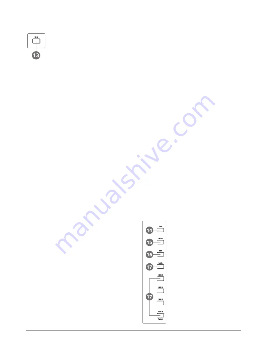
13. Link button
Input channels, aux buses, and subgroups can be linked as
a stereo pair. It will illuminate if the stereo link button has
been pressed and enabled. The stereo pairs are predefined
and cannot be changed. They are as follows:
Channels 1 and 2 Channels 13 and 14
Channels 3 and 4 Channels 15 and 16
Channels 5 and 6 Aux 1 and Aux 2
Channels 7 and 8 Aux 3 and Aux 4
Channels 9 and 10 Subgroups 1 and 2 or Aux 5 and 6
Channels 11 and 12 Subgroups 3 and 4 or Aux 7 and 8
A stereo link can be enabled when either channel in the
pair is selected by pressing the Link button. When the Link
button is illuminated which indicates the Stereo Link func-
tion enabled, all DSP setting, subgroup assignments, solo
status and main assignments are passed to the other chan-
nel in the pair.
Link & DCA: After link, the channels can also be grouped to
DCA as stereo channel, but not able to cancel the link in DCA.
On the contrary, if the channel has been grouped to DCA, it
can not link at all, but its paired channel can link. For exam-
ple, channel 5 is linked with channel 6, then both channel
5 and 6 can be grouped to DCA. But if channel 5 has been
grouped to DCA first, it can not link to channel 6, but channel
6 can link to channel 5.
Link & Routing: The two linked channels can route as stereo
channel, while routed channels can also link later.
Please note that this is a nondestructive passing, the other
channel’s previous setting will be restored after the Link but-
ton is disengaged. For example, when Channel 6 has been se-
lected, then press Stereo Link button, all of Channel 6’s setting
will be copied onto Channel 5. The Channel 5’s own setting will
restore after the Link button has been disengaged.
14. Solo button
Press this button will send its channels or buses to the con-
trol room outputs. It will illuminate as has been pressed
and enabled.
15. Mute button
Press this button will mute selected channel and all of its as-
signed outputs. 15
It will illuminate when the button has been pressed and en-
abled.
16. Pan button
Press this button to select the Pan function, then rotate Pa-
rameter Adjust encoder to control signal level from left to
right for the selected input or output bus. If you have adjust-
ed a channel pan, please just touch 2 times on the screen and
make it back to the centre position. The LCD display shows
the setting in real time. If two channels have been linked as
stereo pair, the LCD display will automatically change to ste-
reo pan.
17. Main & SUB1-4 buttons
The selected channel can be assigned to SUB group outputs
1-4 and Main Outputs by pressing the corresponding button.
But if SUB mode is switched to AUX mode, the SUB1-4 button
can not active.
The main 20 inputs, USB In, and FX1-2 can be assigned to any or
all of the output Subgroups, Aux Sends and the main outputs.
Subgroups can only be assigned to the main outs. The 4 aux
sends cannot be assigned to a subgroup or to the main outputs.
p. 16
LIVE 16XL
ENGLISH VERSION
Summary of Contents for LIVE 16XL
Page 2: ...p 2 LIVE 16XL ENGLISH VERSION p 2 LIVE 16XL ENGLISH VERSION...
Page 4: ...Index p 4 LIVE 16XL ENGLISH VERSION...
Page 5: ...Table of contents p 5 LIVE 16XL ENGLISH VERSION...
Page 10: ...Control Page of output channel AUX1 4 SUB1 4 p 10 LIVE 16XL ENGLISH VERSION...
Page 51: ...Hookup Diagram...
Page 52: ...Technical information p 52 LIVE 16XL ENGLISH VERSION p 52 LIVE 16XL ENGLISH VERSION...
Page 53: ...Block Diagram p 53 LIVE 16XL ENGLISH VERSION...
Page 107: ...PARA MAS INFORMACION SOBRE ESTE PRODUCTO VISITE LIVE 16XL VERSI N ESPA OL...


