


[logo]
[TITLE]
MARCH 9, 2000
[PART NUMBER]
Audioaccess Trouble Shooting
Page 9
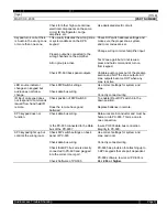
PX-612 RELATED
Problem Encountered
Find the problem component
solution
PX-612 LED indicator
light always stays RED.
Amp is in protect mode.
Check AC line voltage.
Check that speakers are not shorted
and that the impedance is correct.
Check for DC offset for sources or
Preamp.
Check for overheating.
Requires 110VAC constant.
No lower than 4 Ohms per channel.
Change or repair source.
Change or repair Preamp.
Ventilate cabinet.
PX-612 LED indicator
light always stays Yellow.
IE: unit does not come out
of stand-by.
Check input signal from Preamp.
Check continuity of cabling feeding
amp.
Feed a direct signal to Amplifier such as
from a CD player to see if it turns on
and off with signal sensing.
Change or repair defective cable.
PX-612 LED indicator
light always stays Green.
IE: Amp is always ON
Is there a cable system attached to
the Audioaccess controller?
Is there a local system sharing
sources with the system? Some
receivers short the input to ground
when in the stand-by condition.
Disconnect cable. If the problem goes
away then use a ground loop isolator in
line with the cable input feed.
Disconnect wiring feeding the local
system. If problem goes away use an in
line (RCA style) ground loop isolator to
bring the signal to the local system.
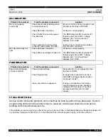
MULTI SYSTEM RELATED
Problem Encountered
Find the problem component
solution
Subsequent units in multi
system (other than
system 1) always jump
back to FM after another
source key has been
pressed.
PX-connect or MRX-connect
sequence was not performed
correctly.
After running the connect sequence be
sure to press the “ALL OFF” button on
front panels from the highest system
number to the lowest system number.
Subsequent units in multi
system do not respond to
any commands other than
front panel.
Check Data bus connection.
Check keypad connections.
Check bus fuse on back panel.
Voltage between pins 1 & 4 should
be between 8 to 13 VDC.
Connect with correct polarity while not
connecting the RED (or power) wire
between systems.
Make sure keypads are correctly
connected for polarity.
Change fuse w/ 1.5 amp slo-blo
Summary of Contents for PX-603
Page 2: ......
Page 3: ......
Page 4: ......
Page 5: ......
Page 6: ......
Page 7: ......
Page 8: ......
Page 9: ......
Page 10: ......
Page 11: ......
Page 12: ......
Page 13: ......
Page 14: ......
Page 15: ......
Page 16: ......
Page 17: ......
Page 18: ......
Page 19: ......
Page 20: ......
Page 21: ......
Page 22: ......
Page 23: ......
Page 24: ......
Page 25: ......
Page 26: ......
Page 27: ......
Page 28: ......
Page 29: ......
Page 30: ......
Page 41: ......
Page 42: ......
Page 43: ......
Page 44: ......
Page 45: ......
Page 46: ......
Page 47: ......
Page 48: ......
Page 49: ......
Page 50: ......
Page 59: ...PX 603 EPROM Replacement ...
Page 64: ......
Page 65: ......
Page 67: ......
Page 68: ......


