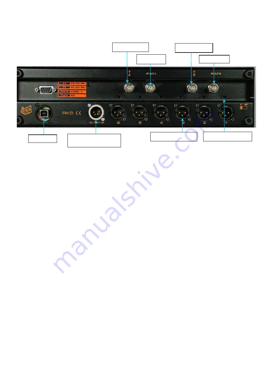
Rear panel view
Installing the DX2040 receivers.
Holding each receiver with the LEMO connector at the bottom and facing towards the rack,
tilt the receiver downwards slightly and engage the bottom of the receiver into the slot in the
RK6 front panel. Raise the receiver until it is parallel to the guide rails and slide it fully into
the slot. Press firmly on the receiver until you feel the connectors engage. Do not use undue
force.
Repeat for all the receivers that you are using.
Setting up the RK6 rack.
Ensure that the power switch on the rear of each receiver is ON (in the down position).
The receivers are powered from the RK6 rack. If batteries are left in the receivers, they will
not be connected. However, we recommend that batteries are removed if the receivers are to
be left in the rack for long periods.
Connect the supplied DC power source to the 4-pin XLR connector on the rear panel of the
rack.
Switch on the RK6.
The microprocessor in the RK6 will detect the presence of the DX2040 receivers in the slots.
The rack will interrogate each receiver via its IrDA infra-red interface and store the frequency
table and settings for each one. During this period, an hourglass icon will be displayed in the
appropriate position on the screen.
Once all the installed receivers have been logged in, the screen will display the current RSSI
levels, AF level, transmitter battery level and diversity state for each one.
Connect an antenna to each of the 2 BNC connectors on the rear panel marked with an
antenna icon and the letter A or B.
If the receivers are already programmed to the required frequencies and attenuator settings
and passive antennae are being used, the RK6 is now ready to use.
USB socket
Industry standard 4pin
male XLR power socket
3 pin XLR socket x 6
Phase change switch x 6
RF output A
RF output B
Antenna input A
Antenna input B


