5
Initial Setup
Unpacking
Assembling the Turntable
Setting the Pre-amplifier Selector Switch
Assembling the Tonearm
Figure 4 – Headshell with fitted cartridge
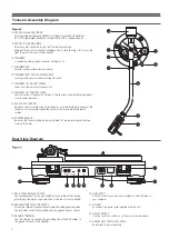
1. Remove the nylon tie used to secure the tonearm during shipment.
Temporarily secure the tonearm in the tonearm rest with the locking
clamp. [Figure 2, page 4, #12].
2. Attach the headshell/cartridge assembly by inserting it into the socket
at the front of the tonearm [See Figure 4]. It is good practice to hold
the headshell assembly by the left and right edges of the headshell to
reduce the possibility of damaging the stylus or disrupting the
cartridge wiring.
English
The AT-LP5 requires some assembly before first use.
IMPORTANT: Do not connect the AC power cable until assembly is
complete.
For increased flexibility of use, this turntable has an internal stereo
phono pre-amplifier. The pre-amplifier selector switch located in the
rear panel of the turntable [See Figure 3, page 4, #18], selects the
internal stereo pre-amplifier (LINE), or bypasses the pre-amplifier
(PHONO OUT) for use with systems having specialized magnetic
phono input sockets. The audio output cable’s Red RCA-type plug is
the Right channel; the White plug is the Left channel.
If the system you are using has a phono input, set the pre-amplifier
selector switch to the PHONO position and connect the turntable’s output
cables to the phono inputs on your system, observing Red for Right
channel and White for Left channel, in addition connect the grounding
line attached to the stereo RCA / RCA cables to the ground terminals.
If your system does not have a magnetic phono input, set the
pre-amplifier selector switch to LINE and connect the turntable’s output
to the Auxiliary (AUX) or other high-level inputs on your system,
observing Red for Right channel and White for Left channel.
When using the turntable with a computer sound card, set the switch
to LINE and connect the turntable's stereo output to the audio line input
on the computer sound card. Note: An audio adapter (not included) may
be required to interface the two RCA outputs (L + R) of the turntable to
the computer sound card input.
Carefully unpack the turntable and verify that the following parts are
included and intact:
• Rubber mat
• Dust cover (above the turntable)
• Platter (under the turntable)
• Counterweight (accessory section)
• AT-HS10 headshell with pre-mounted AT95EX Dual Moving
Magnet stereo cartridge (accessory section)
• Exclusive AT-HS10 Lightweight Headshell
• Power cable
• USB cable
• Dual RCA male to dual RCA male cable with grounding line
• Audacity software (CD)
WE RECOMMEND THAT YOU SAVE ALL PACKAGING MATERIALS
FOR POSSIBLE FUTURE STORAGE, MOVING OR SHIPPING.
Assembling the Turntable Platter and Rubber Mat
Setting Tonearm Balance and Tracking Force
Tonearm Setup
3. While holding the headshell in position, rotate the headshell locking
ring counter-clockwise (to the left). As the ring turns, it pulls the
headshell into its seated position (rotate the ring a full turn to the right
to permit removal of the headshell).
4. With the black dial toward the front, use a screwing motion to attach
the counterweight to the arm extending back from the tonearm pivot
[Figure 2, page 4, #16]; the counterweight will engage the spiral groove
in the rear arm section and move forward.
1. Carefully place the turntable platter on the center spindle, making
certain the platter is fully seated on the spindle.
2. Place the rubber mat on top of the platter.
Assembling the Dust Cover
1. Insert the T-shaped ends of the dust cover hinges into the two hinge
receptacles located at the back of the turntable housing. When properly
installed, the flat part of the cover hinges should be facing away from
the turntable housing at about a 45° angle.
1. Set the anti-skate adjustment to “0”. [Figure 2, page 4, #15].
2. Remove the clear protective stylus cover, carefully sliding it
straight
forward
, off the front of the cartridge.
3. Continuing to gently hold the headshell to stabilize the tonearm, release
the tonearm locking clamp. At this point, the tonearm is unbalanced and
free to swing.
4. Continuing to gently hold the headshell, carefully rotate the counter-
weight until the tonearm is horizontally balanced and hovers freely just
above the platter without touching the cartridge on the platter surface.
5. Lock the tonearm back into the tonearm rest.
6. While holding the counterweight steady, and without any rotation,
carefully rotate only the black stylus force gauge ring (which turns
independently of the counterweight) until the “0” on the gauge ring
lines up with the centerline marked along the top of the rear arm.
7. Refer to the cartridge manufacturer’s specifications for recommended
tracking force. Rotate the entire counter-weight counterclockwise
without touching the black gauge ring, moving the counterweight
forward, until the desired value on gauge ring lines up with the
centerline marked on the rear arm. Refer to the specifications section for
tracking force value for the cartridge that shipped with the turntable,
typically 2 g for the AT95EX.
To ensure the cartridge tracks properly in a record, the tonearm
balance and tracking force must be carefully set to the cartridge
manufacturer’s specifications. Failure to properly set up the tonearm
assembly can cause damage to the cartridge stylus and/or records.
Note: Once the stylus protective cover has been removed and the
tonearm locking clamp has been released,
take extreme care not
to damage the stylus
. Do not allow it to drag or scrape across the
rubber mat nor the record.
Setting Anti-skate
A small outward “anti-skating” force can be applied to the tonearm to
compensate for the “skating” force that pulls the arm toward the center
of the record when rotating. For best performance during normal
turntable use, set the anti-skate control knob [Figure 2, page 4, #15] to
the same setting as the tracking force dial. Refer to the specifications
section for tracking force value of the cartridge that shipped with the
turntable.
Summary of Contents for AT-LP5
Page 47: ......


