background image

INSTRUCTIONS 

12   


Profinet Card (710-16502-00C) 

Parameter  Parameter name 

Description 

40D 

Ground fault action


Selects the soft starter’s response to the 
protection event. 

40E 

Ground fault CT ratio 

Set to match the ratio of the ground current 
measuring CT. 


6.


Operation 

The device has been designed for use in a system complying with the Profinet 
standard.    For successful operation, the controller must also support all functions 
and interfaces described in this document. 


6.1


Device classification 

The Profinet Card is a Profinet IO-Device and must be managed by an IO-Controller 
over Ethernet. 


6.2


Ensuring safe and successful control 

Data written to the device will remain in its registers until the data is overwritten or 
the device is reinitialised.   
If the soft starter may be controlled via Command Override (parameter 7A) or may be 
disabled via the reset input (terminals 10, 11) fieldbus commands should be cleared 
from the registers. If a command is not cleared, it will be re-sent to the starter once 
fieldbus control resumes. 


6.3


Feedback LEDs 

Port 1

Port 2

Keypad

LINK 2

TX/RX2

LINK    1

TX/RX1

ERROR

STATUS

17821.

A


LED name  LED state  Description 

Power 

Off 

Device is not powered up. 


On 

Device is receiving power. 

Error 

Off 

No error. 


Flashing 

Connection not established. 


On 

No physical link or slow physical link. 
No configuration. 

Status 

Off 

No error. 


Flashing 

DCP signal service initiated via the bus. 

Link x 

Off 

No network connection. 


On 

Connected to a network. 

TX/RX x 

Flashing 

Transmitting or receiving data. 


Summary of Contents for PROFINET CARD

Page 1: ... Specifications 23 Compatibility This manual is suitable for Profinet Card Profinet Card with Ground Fault These cards are suitable for use with EMX4e and EMX4i soft starters The available features may vary according to the model and version of the starter This user manual is intended for use with version 3 x of the Profinet Card Version 2 x of the Profinet Card does not support custom users or Io...

Page 2: ...ing from the use or application of this equipment Failure to follow the information and instructions in this manual will void the warranty Warnings It is the installer s responsibility to follow all instructions in this manual and to follow correct electrical practice WARNING For your safety isolate the soft starter completely from mains voltage before attaching or removing accessories WARNING Ins...

Page 3: ...evice with third party products including PLCs scanners and commissioning tools contact the relevant supplier 1 2 Connections 23081 A 2 3 1 1 2 x RJ45 ethernet ports supporting line star ring and loop network topologies 2 2 pin connector for ground fault CT selected models 3 DB9 connector for optional remote keypad 1 3 Communication protocols The Profinet Card supports the following protocols Prof...

Page 4: ...INSTRUCTIONS 4 Profinet Card 710 16502 00C 1 Soft starter 2 Network switch 3 IoT connection MQTT OPC UA 4 Industrial ethernet connection to programmable logic controller ...

Page 5: ...ice has two Ethernet ports If only one connection is required either port can be used Cables Use Category 5 5e 6 or 6e cable to connect to the device EMC precautions To minimise electromagnetic interference Ethernet cables should be separated from motor and mains cables by 200 mm If the Ethernet cable must cross motor or mains cables the crossing should be at an angle of 90 2 3 Network establishme...

Page 6: ...uration Tool 1 Start the Ethernet Device Configuration Tool 2 Click on Search Devices The software will search for connected devices 3 To configure a device name click Configure then select Device Name NOTE The Error LED is on if the device is not configured If the device is configured but is not passing I O data the Error LED will flash The Error LED will be active during the configuration proces...

Page 7: ...a link across terminals 10 11 on the soft starter 3 3 On board web server Settings in the Profinet Card can be configured via the card s web server Connect to the device To configure settings using the on board web server the card must be installed in a soft starter control power must be available and the card and computer must both be connected to the Ethernet network The computer must use a fixe...

Page 8: ...support custom users The Profinet Card supports multiple users and levels of privilege Users can view the home screen and IP address settings Supervisors can view the home screen and IP settings and can change configuration settings Administrators can view the home screen change configuration settings and add or delete users To add a new user 1 Connect to the web server then click Administration 2...

Page 9: ...ing over IoT The card cannot control or program the soft starter NOTE Version 2 x of the Profinet Card does not support IoT operation Configure MQTT settings 1 Connect to the web server then click Configuration MQTT Client 2 Tick the Enable checkbox to enable MQTT client operation The MQTT client is enabled by default 3 Click Connection then configure the settings as required 4 Use Connection Acti...

Page 10: ...onfiguration OPC UA Server 2 Tick the Enable checkbox to enable OPC UA client operation The OPC UA client is enabled by default 3 Click Server Configuration then configure the settings as required 4 Use Actions to select the actions for different object instances 5 Click Submit to save all settings in the card ...

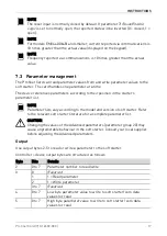
Page 11: ...oft starter can be configured to trip at 1 A 50 A If ground fault current rises above 50 A the soft starter will trip immediately 5 2 Connect the CT to the ground fault inputs To use ground fault protection a common mode current transformer CT must be installed around all three phases Use a 1000 1 or 2000 1 CT with rating of 5 VA and set parameter 40E Ground Fault CT Ratio to match Connect the CT ...

Page 12: ... device will remain in its registers until the data is overwritten or the device is reinitialised If the soft starter may be controlled via Command Override parameter 7A or may be disabled via the reset input terminals 10 11 fieldbus commands should be cleared from the registers If a command is not cleared it will be re sent to the starter once fieldbus control resumes 6 3 Feedback LEDs Port 1 Por...

Page 13: ...ry motor set when starting 2 Use secondary motor set when starting 3 Reserved 4 0 stop action will be as selected in the soft starter 1 stop action will be a coast to stop 5 to 7 Reserved 1 0 0 Stop 1 Start 1 to 2 Reserved 3 1 Reset 4 to 7 Reserved 2 to 5 Parameter management refer to Parameter management on page 17 7 2 Status information device to controller Starter status information is always a...

Page 14: ...ulation reset input is open 6 Tripped 7 Menu open cannot start 8 Jog forward 9 Jog reverse 4 0 Negative phase sequence 1 Positive phase sequence 5 1 Current exceeds FLC 6 0 Uninitialised 1 Initialised 7 1 Communication error between device and soft starter 8 to 15 Reserved Bytes 4 5 Trip code Bits Details 0 to 15 Refer to Trip codes on page 18 Bytes 6 7 Motor current Bits Details 0 to 15 Average r...

Page 15: ... 1 Ready 2 Starting 3 Running 4 Stopping 5 Not ready restart delay restart temperature check run simulation reset input is open 6 Tripped 7 Programming mode 8 Jog forward 9 Jog reverse 5 1 Warning 6 0 Uninitialised 1 Initialised 7 Command source 0 Network Timer 1 Remote Keypad Digital Input Clock 8 Reserved 9 0 Negative phase sequence 1 Positive phase sequence 10 to 15 Reserved 20 21 Current 0 to ...

Page 16: ... 36 37 Current 0 to 13 Phase 3 current rms 14 to 15 Reserved 38 39 Voltage 0 to 13 Phase 1 voltage rms 14 to 15 Reserved 40 41 Voltage 0 to 13 Phase 2 voltage rms 14 to 15 Reserved 42 43 Voltage 0 to 13 Phase 3 voltage rms 14 to 15 Reserved 44 45 Parameter list 0 to 7 Parameter list minor revision version number 8 to 15 Parameter list major version 46 47 Digital input state For all inputs 0 open 1...

Page 17: ...ding to their position in the starter s parameter list NOTE Parameter lists vary according to the model and version of soft starter Refer to the relevant soft starter literature for a complete parameter list CAUTION Changing the values of the Advanced parameters parameter group 20 may cause unpredictable behaviour in the soft starter Consult your local supplier before adjusting the Advanced parame...

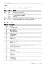
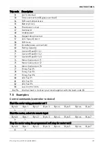
Page 18: ...eter value read from soft starter 7 4 Trip codes Trip code Description 255 No trip 1 Excess start time 2 Motor overload 3 Motor thermistor 4 Current imbalance 5 Frequency 6 Phase sequence 7 Overcurrent 8 Power loss 9 Undercurrent 10 Heatsink overtemperature 11 Motor connection 12 Input A trip 13 FLC too high 14 Unsupported option function not available in inside delta 15 Communications card fault ...

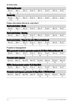
Page 19: ... Motor Connection T2 76 Motor Connection T3 77 Firing Fail P1 78 Firing Fail P2 79 Firing Fail P3 80 VZC Fail P1 81 VZC Fail P2 82 VZC Fail P3 83 Low Control Volts 84 96 Internal fault x Contact your local supplier with the fault code X 7 5 Examples Control commands controller to device Start the motor using parameter set 1 Byte 0 Byte 1 Byte 2 Byte 3 Byte 4 Byte 5 Byte 6 Byte 7 4 1 Start the moto...

Page 20: ...control status Tripped trip code 4 Current imbalance Byte 0 Byte 1 Byte 2 Byte 3 Byte 4 Byte 5 Byte 6 Byte 7 6 0 4 0 Parameter management Write parameter to starter parameter number 2 1B Motor Full Load Current 55 Byte 0 Byte 1 Byte 2 Byte 3 Byte 4 Byte 5 Byte 6 Byte 7 2 4 55 0 Parameter write response Byte 56 Byte 57 Byte 58 Byte 59 Byte 60 Byte 61 Byte 62 Byte 63 2 0 55 0 EMX4e Read parameter nu...

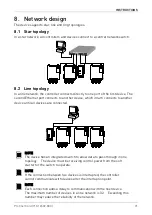
Page 21: ... in turn connects to another device until all devices are connected 14695 A NOTE The device has an integrated switch to allow data to pass through in line topology The device must be receiving control power from the soft starter for the switch to operate NOTE If the connection between two devices is interrupted the controller cannot communicate with devices after the interruption point NOTE Each c...

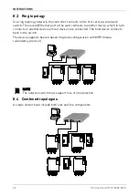
Page 22: ...nnects to another device which in turn connects to another device until all devices are connected The final device connects back to the switch The device supports beacon based ring node configuration with MRP media redundancy protocol 14696 A NOTE The network switch must support loss of line detection 8 4 Combined topologies A single network can include both star and line components 14700 A ...

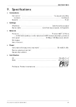
Page 23: ...ame Automatically assigned configurable Network Protocols Profinet MQTT OPC UA DHCP ACD address conflict detection MRP media redundancy protocol Link speed 10 Mbps 100 Mbps auto detect Full duplex Auto crossover Power Consumption steady state maximum 35 mA 24 VDC Reverse polarity protected Galvanically isolated Certification CE EN 60947 4 2 RCM IEC 60947 4 2 Profibus Profinet International ...

Page 24: ...INSTRUCTIONS 24 Profinet Card 710 16502 00C ...

Reviews: