ATX Maxnet II QMP 1000 Installation & Operation Manual Download Page 13

STATUS MONITORING

3.  Status Monitoring

3.1.  Chassis Interface Options

The Active MAXNET II product line can be monitored and controlled in either of two ways:

a)  A free, web-based interface. This comes pre-installed on every active chassis and provides a user friendly method 

of  configuring  the  administrative  set-up  and  all  monitoring  and  control.  It  is  based  on  SNMP,  but  requires  little 

knowledge of SNMP. Any Internet browser, such as Internet Explorer, is all the software that is required.

b)  Any third-party SNMP Management software (e.g. 

www.castlerock.com


www.ndt-inc.com/SNMP/MIBrowser.html

may be purchased separately. These suites tend to be expensive and 

not as user friendly as the web interface. The web interface is also still required for administrative set-up. The 3

rd


party interface is recommended only for systems that have an existing SNMP architecture. All MIBs (Management 

Information Bases) are freely downloadable from the SCTE website (

www.scte.org/standards

). ATX was able to 

support all modules using the SCTE standard HMS MIBs, so no custom MIBs are required.

3.2.  SCTE HMS MIB Software Definition of Module

The headend RF Amp MIB is used to provide only an Output RF detector value, allowing HI and LO alarm thresholds to be 

set.

3.3.  Web Interface

The MAXNET II active chassis uses an integrated web page to supplement the SNMP management. All configurations of 

the chassis (static IP address, trap/email recipients, firmware upgrades, etc) must be done through the web page. Simply 

use any web browser (Internet Explorer, Firefox, etc.) and enter the IP address of the chassis as the URL – see Section 

3.5.1. for default parameters when shipping from ATX. Login as administrator (select administrator and type in: admin) to 

modify configuration and have full read/write access to monitor and control modules. Login as Operator to have full read/

write access or login as observer to have read-only access. There is only one password per login level – see Section 3.5.1. 

for default parameters when shipping from ATX. 

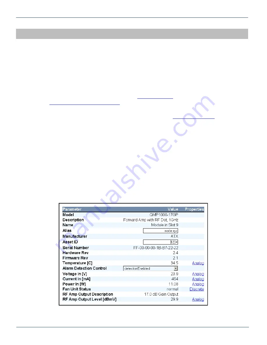
Figure #5:  Web Interface Parameter Page (example)

          MAXNET

®

 II – QMP1000 Forward RF Amplifier – Installation & Operation Manual 

3-1


CHAPTER 3:  STATUS MONITORING

CHAPTER 2:  INSTALLATION

Summary of Contents for Maxnet II QMP 1000

Page 1: ...QMP1000 Forward RF Amplifier Installation Operation Manual CCAP Compliant 1 2 GHz ...

Page 2: ... by one or more U S or foreign patents Other non ATX product and company names in this manual are the property of their respective companies Although every effort has been taken to ensure the accuracy of this document it may be necessary without notice to make amendments or correct omissions Specifications subject to change without notice ...

Page 3: ...is Interface Options 3 1 3 2 SCTE HMS MIB Software Definition of Module 3 1 3 3 Web Interface 3 1 3 4 Updating Active Chassis Firmware 3 2 3 5 Factory Reset 3 2 4 STATUS MONITORING FEATURES 4 1 4 1 SNMP Parameters 4 1 4 2 SNMP MIBs Required for QMP1000 4 2 5 MAINTENANCE TROUBLESHOOTING 5 1 5 1 Maintenance 5 1 5 2 Troubleshooting 5 1 6 SERVICE SUPPORT 6 1 6 1 Contact ATX Networks 6 1 6 2 Warranty I...

Page 4: ... Tables 1 Ordering Information 1 1 2 Technical Specifications 1 3 3 LED Status Indications 2 2 4 Plug in PAD Specifications 2 3 5 Plug in 1 GHz EQ Specifications 2 3 6 Plug in 1 218 EQ Specifications 2 3 7 Plug in PAD EQ Ordering Information 2 4 8 Common Module Parameters 4 1 9 QMP1000 SNMP Parameters 4 1 10 General SCTE HMS MIBs Required 4 2 11 QMP1000 SCTE HMS MIBs Required 4 2 ii MAXNET II QMP1...

Page 5: ... conjunction with Mini RG 59 Type coaxial cable Also featured are front access alarm LED indicator 20 dB test points and the capability of module status monitoring through SNMP based Managers The MAXNET II SNMP interface is HMS compliant Please refer to the web page for up to date specifications www atxnetworks com Table 1 Ordering Information MAXNET II QMP1000 Forward RF Amplifier Installation Op...

Page 6: ...PTER 1 PRODUCT DESCRIPTION RF DETECTOR 24 VDC CHASSIS COMM RF OUTPUT RF INPUT 20 dB OUTPUT TEST POINT 20 dB INPUT TEST POINT FAN ACTIVE FUSE POWER FAN CTRL PWR ALARM MONITOR CONTROL PAD EQ PAD EQ Single Stage Forward Amplifier RF DETECTOR 24 VDC CHASSIS COMM RF OUTPUT RF INPUT 20 dB OUTPUT TEST POINT 20 dB INPUT TEST POINT ACTIVE FUSE POWER FAN CTRL FAN MONITOR CONTROL PWR ALARM PAD EQ Dual Stage ...

Page 7: ...1 2 Technical Specifications Table 2 Technical Specifications MAXNET II QMP1000 Forward RF Amplifier Installation Operation Manual 1 3 CHAPTER 1 PRODUCT DESCRIPTION ...

Page 8: ...CHAPTER 1 PRODUCT DESCRIPTION 1 4 MAXNET II QMP1000 Forward RF Amplifier Installation Operation Manual This page left intentionally blank ...

Page 9: ...e active chassis back plane If the module is installed properly the amplifier will make contact with the 24 VDC power bus in the chassis and if there is a MAXNET II Power Supply Module installed in the chassis and it is plugged into the respective power source the module s PWR Power LED indicator will light green To remove an amplifier module from the chassis gently lift the front handle and pull ...

Page 10: ...gure 1 and Figure 2 2 4 Amplifier Set up 2 4 1 Amplifier LED Indicators The MAXNET II QMP1000 Amplifiers have two LED indicators PWR and ALM a The PWR Power LED verifies that the amplifier module is receiving power from the MAXNET II Power Supply through the 24 VDC Chassis Bus The PWR LED is always solid green when the module is powered If no powering is available then the PWR LED is off The PWR L...

Page 11: ...o PAD EQ locations By default amplifiers are shipped with plugged in 0 dB values in all four locations Within a module the PAD s EQ s on the left side are connected to the RF Input and the ones on the right side are connected to the RF Output Single Stage Amplifier or interstage Dual Stage Amplifier Table 4 Plug in PAD Specifications Table 5 Plug in 1 GHz EQ Specifications Table 6 Plug in 1 218 GH...

Page 12: ...ion Operation Manual Part Number Description MP PAD Plug in Pad 1218 MHz dB value 0 20 dB must order in quantities of 10 MP EQ Plug in EQ 1000 MHz dB value 1 5 10 5 dB must order in quantities of 10 MP EQLH Plug in EQ 1218 MHz dB value 1 5 10 5 dB must order in quantities of 10 MPPT Pad EQ Insertion and Extraction Tool ...

Page 13: ...as able to support all modules using the SCTE standard HMS MIBs so no custom MIBs are required 3 2 SCTE HMS MIB Software Definition of Module The headend RF Amp MIB is used to provide only an Output RF detector value allowing HI and LO alarm thresholds to be set 3 3 Web Interface The MAXNET II active chassis uses an integrated web page to supplement the SNMP management All configurations of the ch...

Page 14: ...s powered until it completes a reboot j Optionally the chassis may now be factory reset to restore all IP settings to factory defaults Read the Factory Reset section fully before doing this to know what data will be lost when doing this 3 5 Factory Reset A factory reset will restore the chassis to the state which it left the ATX production facility 3 5 1 Parameters that will be Changed IP address ...

Page 15: ... entPhysicalAssetID Serial No Module s serial number entPhysicalSerialNum Hardware Rev Hardware rev of module entPhysicalHardwareRev Firmware Rev Firmware rev of module entPhysicalFirmwareRev Temperature C Module s current heatsink temperature heCommonTemperature Alarm Detection Control detectionEnabled normal operation with active alarms detectionDisabled used to temporarily disable alarms traps ...

Page 16: ...ifier Installation Operation Manual HMS SCTE SCTE ROOT 028 36 SCTE HMS ROOTS 072 37 SCTE HMS HEADENDIDENT MIB 114 38 11 SCTE HMS HE COMMON MIB 111 84 1 SCTE HMS PROPERTY MIB 026 38 1 SCTE HMS HE FAN MIB 117 84 3 SCTE HMS HE POWER SUPPLY MIB 116 84 2 HMS SCTE SCTE HMS HE RF MIB 133 83 4 SCTE HMS HE RF AMP MIB 131 94 1 CHAPTER 4 STATUS MONITORING FEATURES ...

Page 17: ... slot of the chassis and likely the connector on the back rail is damaged Contact ATX and report a defective chassis If this does not fix the problem then contact ATX and report a defective module 5 2 2 Chassis Yellow COM LED Not Blinking It is normal for the round LED near the RJ45 port at the rear of the chassis to be solid ON or OFF during various states of system boot up If the chassis has bee...

Page 18: ...ry removing and replacing the module in a different slot Verify that the green power LED is solid and the red LED is either off or blinking quickly approx half second on half second off If the LEDs are not as stated see the appropriate troubleshooting section 5 2 5 Module Power LED Off or Intermittent Check the 24V green LED on the rear of the chassis If it is off then the problem is that the chas...

Page 19: ...2 8 Temperature Fan Fault Alarm on any MAXNET II Active Module Check to see if the module fan is operating If not replace with a new fan from ATX Fan Part MPFANA using the below procedure 5 Install replacement fan in the opposite order shown Ensuring that a The red and black wires are aligned b The labelled side of the fan faces inward toward the module c The wires do not bunch up behind the fan i...

Page 20: ...CHAPTER 5 MAINTENANCE TROUBLESHOOTING 5 4 MAXNET II QMP1000 Forward RF Amplifier Installation Operation Manual This page left intentionally blank ...

Page 21: ...covers manufacturer s defects or failures 6 3 Safety IMPORTANT FOR YOUR PROTECTION PLEASE READ THE FOLLOWING WATER AND MOISTURE Care should be taken so that objects do not fall and liquids are not spilled into the enclosure through openings POWER SOURCES The device should be connected to a power supply only of the type described in the operating instructions or as marked on the device GROUNDING OR...

Page 22: ...n Canada Rev 09 15 ANW0747 1 501 Clements Road West Ajax ON L1S 7H4 Canada Tel 1 905 428 6068 Toll Free 1 800 565 7488 Fax 1 905 427 1964 Toll Free Fax 1 866 427 1964 www atxnetworks com support atxnetworks com ...

Reviews: