
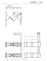

7.1
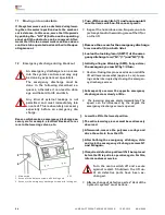
Moving onto an obstacle
If the system moves onto an obstacle during lower-
ing, then it remains in position due to the mechani-
cal resistance. In this case, move the lift upwards
by pushing the
o
"Lift" (2) button on the operating
panel until the obstacle can be removed. After-
wards the lift is in a normal work condition and can
continue to be operated as described in the oper-
ating manual.
7.2
Emergency discharge during blackout
An emergency discharge is an access
into the system controls and may only
be done by experienced specialists.
The emergency discharge must be
done in the following described se -
quence, otherwise it can lead to dam-
age and hazard to life and limb,
Any kind of external leakage is not
permitted and must immediately tak-
en care of. This is absolutely necessary
especially before an emergency dis-
charge.
Reason which make an emergency discharge nec-
essary are for example, electrical blackout, for er-
rors in the lowering valves, etc.
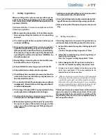
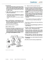
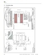
1
5
6
1 Main switch
003
5 Access to the balance screws with locking nuts
6 Access to the emergency discharge screws with locking nut
)
Turn off the main !;itch (1) and !ecure again!t
unauthorized switch on. Disconnect power.
!
Inspect the hazardous area. No person or ob-
ject may stand in the working area of the lift, or
on the lift.
)
Remove the covers for the emergency discharge
!cre; acce!!e! (6) on both !ide!.
)
Loo!en the locking !cre;! (SW17) of the emer-
gency di!charge !cre;! "N1" (1") and "N2" (15).
)
Initially, u!ing an Allen key (SW5), !lo;ly un!cre;
the emergency screw N1 by 1/4 turn.
!
Caution: During this process a drive on rail of the
lift will lower somewhat (approx. 5 cm). Lower-
ing can be interrupted by closing the emergen-
cy discharge screw.
)
Subsequently unscrew the opposite emergency
discharge screw slowly a little.
!
The lowering process starts immediately. The
speed can be influenced by the degree the
emergency discharge screw is opened.
)
Lower the lift to the lowest position.
)
The entire lowering process must be continuously
observed.
)
Afterwards, remove the polymer overlays and
drive the vehicle from the lift.
)
After fini!hing the emergency di!charge, clo!e
and lock the emergency discharge screws N1
and N2 again.
)
If required, defective part! mu!t fir!t be replaced
before the lift is put into operation again. For this,
inform customer service.
Turn the main switch off and secure
against restart. Shutdown the lift un-
til all defective parts have been ex-
changed.
!
After exchange of defective parts a "Vent of the
hydraulic system" must be done.
64
JUMBO LIFT 3200 NT - HYMAX XX 3200 PH
19.05.2015
AD H9402
Summary of Contents for HYMAX XX 3200 PH
Page 3: ...ENGLISH Translation...


