background image

1

1.9


Select Main tab


1.9.1

 Device and Signature Bytes = ATtiny88


1.9.2

 Programming Mode and Target Settings = ISP Mode


1.9.2.1

 Settings ISP Freq = 200.0kHz (click Write)

1.10


Select HW Settings tab


1.10.1

 VTarget = Target Voltage: 3.3V (click Write)

1.11


Select Program tab


1.11.1

 Flash


1.11.1.1

 Input HEX File = C:\Program Files\Atmel\Atmel_QTouch_Libaries_4.3\Generic_QTouch_ 


   Libraries\AVR_Tiny_Mega_XMega\QTouch\example_projects\QT600_ATtiny88_gnu.hex
  

1.11.1.2

 Click Program (STATUS LED on Interface Board turns red during programming then back to    


green when programming is complete)

1.12

 Disconnect the USB cable from PC

1.13

 Remove the 6-conductor ribbon cable

1.14

 Connect the 10-conductor ribbon cable between the TOUCH DATA headers on the ATtiny88 and   


        interface boards

1.15

 Reconnect the USB cable to PC

1.16

 In Atmel

®

 AVR Studio

®

, click on the ‘QT’ icon         in the toolbar to launch Atmel QTouch Studio

®

1.17

 In QTouch Studio


1.17.1

 Make sure that the Application Mode on the left side is set to 

Analysis Mode


1.17.2

 Just below (under Touch Data Read Control), click 

Start Reading


1.17.3

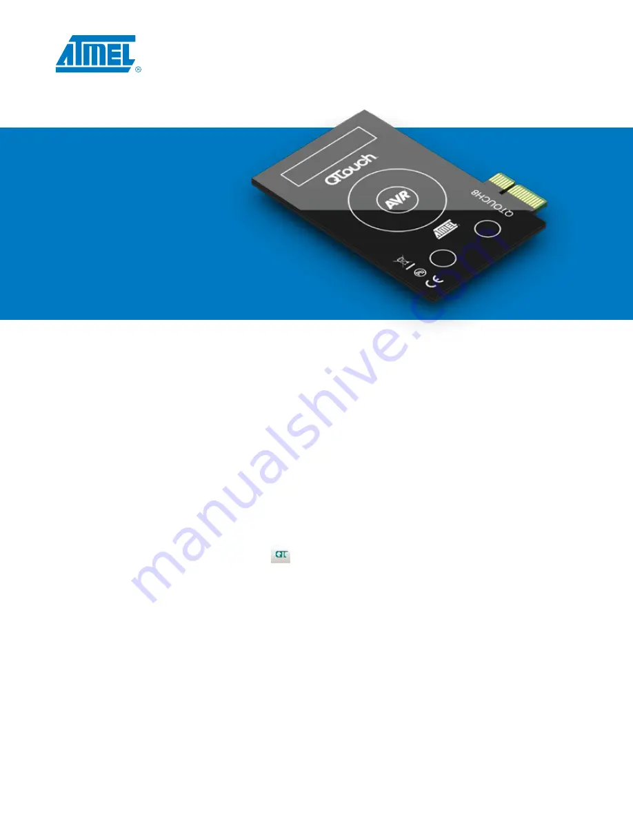
 QTouch Studio is now reading touch data from your QT600. You will see changes in the Virtual Kit View    


           as you touch the sensor regions on the QTouch8 board.

3

Program 
and run 
the demo

Summary of Contents for QT600

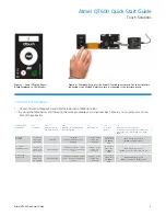
Page 1: ...Atmel QT600 Quick Start Guide Touch Solutions...

Page 2: ...o version 4 3 or later Visual Studio NET version 3 5 or later Atmel AVR Studio version 4 18 or later AND ALL Service Packs SPx Atmel QTouch Library version 4 3 or later GNU Compiler Download at http s...

Page 3: ...oard to the ATtiny88 board 1 6 Connect the USB cable between your PC and the QT600 Interface board Three LEDs should light up then hold the button down for five seconds until the Touch Data LED turns...

Page 4: ...en back to green when programming is complete 1 12 Disconnect the USB cable from PC 1 13 Remove the 6 conductor ribbon cable 1 14 Connect the 10 conductor ribbon cable between the TOUCH DATA headers o...

Page 5: ...ge 3 3V click Write 10 conductor ribbon cable into TOUCH DATA QTouch example_projects QT600_ATtiny88_gnu hex ATouch16 ATXMEGA128A1 10 conductor ribbon cable into JTAG pins ATxmega128A1 JTAG Mode Setti...

Page 6: ...e set up for the Atmel QTouch16 sensor board The sensor board is connected to the Atmel ATXMEGA128A1 which in turn is connected to the interface board 1 5 Figure 5 Atmel QTouch16 sensor board displaye...

Page 7: ...n CPU monitor References Atmel QTouch Library User Guide http www atmel com lib pdf Atmel_TLib3 1_CreateProjectV14_IAR GCC pdf Atmel Touch Sensors Design Guide http www atmel com dyn resources prod_do...

Page 8: ...ANY DIRECT INDIRECT CONSEQUENTIAL PUNITIVE SPECIAL OR INCIDENTAL DAMAGES INCLUDING WITHOUT LIMITATION DAMAGES FOR LOSS AND PROFITS BUSINESS INTERRUPTION OR LOSS OF INFORMATION ARISING OUT OF THE USE O...

Page 9: ...275 ISO 9001 7 812 627 14 35 sales st electron ru 198099 19 100 331...

Reviews: