ATAN0080 [APPLICATION NOTE]
9341B–AVR–02/15
4
2.1.3
Connecting the USB-to-LIN Bridge
The ATmega64M1 Xplained board is used to bridge all LIN messages to USB and vice versa. It can be used with the
supplied GUI as well to monitor the status of the touch buttons, potentiometer and to control the LEDs.
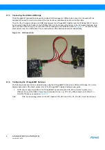
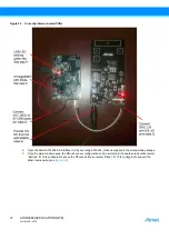
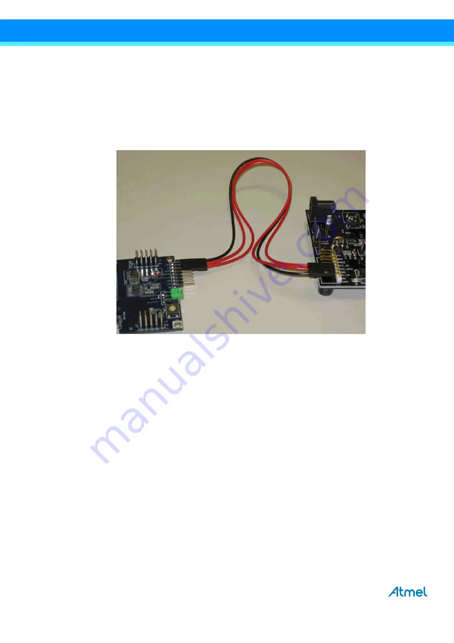
The LIN, LIN_VS (supply voltage), and GND lines between the ATmega64M1 Xplained and the ATABtiny1634-V1 have to
be connected using the J5 header on the ATABtiny1634 and the corresponding header on the ATmega64 Xplained. Care
has to be taken when setting up the connection. When making the connections as shown in
, the outer red and
black cables cross the middle cable. The pin descriptions on the silkscreen should be read carefully.
Figure 2-2.
LIN Connection
2.1.4
Configuring the ATmega64M1 Xplained
The following points need to be considered when using the ATmega64M1 Xplained as a USB-to-LIN bridge. For a more
detailed description of the board, please refer to the ATmega64M1 Xplained hardware user guide.
1.
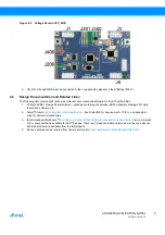
5VDC power supply is provided to the ATmega64M1 by connecting the VCC_MCU (marked in green) (e.g.,
J300/pin) to any of the USB 5V output sources (marked in red, e.g., VCC_5V_USB (onboard) on J406/pin 1 or
J3/pin10). Please see example in
.
Note:
If there is an existing jumper on the J201 header (VCC_MCU and VCC_P3_V3 pins), it must be removed.

