ATAN0080 [APPLICATION NOTE]
9341B–AVR–02/15
20
7.
Using QTouch Debug Mode
The QT600 board must be ordered separately and allows QTouch debug mode to be used. The QT600 board is part of the
tool and available here: http://www.atmel.com/tools/QT600.aspx.
The board must be prepared as described below to use the QTouch debug tools supplied with Atmel
®
Studio.
To prepare the kit for this mode, the ATABtiny1634A-V1 board must be set up as described in
Supply via a VBat Supply Voltage” on page 3
The connections to the ATmega64M1 Xplained board must also be prepared as described in
and the board itself has power supply as described in
Section 2.1.4 “Configuring the
ATmega64M1 Xplained” on page 4
LEDs 1 to 4 on J8 should never be connected, i.e., the jumpers should not be mounted.
When connecting the power and starting the GUI as described in
Section 6. “GUI User Guide” on page 15
, updates should
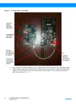
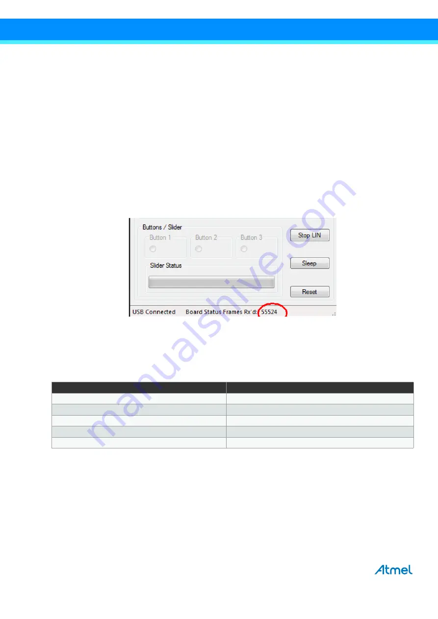
be sent from the board to the GUI. If the connection has been successfully established, this is indicated by the “USB
connected” message and the number of received frames continuously increasing on the lower right corner of the window as
indicated in
.
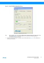
Figure 7-1.
Check Connection
If the connection is working properly, the QTouch debug pins can be enabled by checking the “Enable QTouch Debug”
checkbox.
The QT600 board must then be connected via SPI to the ATABtiny1634A PCB.
illustrates the necessary
connections:
Table 7-1.
Connecting Header Touch Data with J6 on ATABtiny1634A-V1
Header Touch Data on QT600
Header J6 on ATTiny1634
5
5
6
9
7
3
8
7
GND
GND


