background image

Installation Guide

4

AT-OPUS-810M

1

2

3

4

5

6

7

8

1

2

3

4

5

6

7

8

9

10

AUD

IO IN

1

2

1

2

3

4

5

6

7

8

9

10

LAN

DEB

UG

IR IN

RS-2

32

RX

S

TX

R

L

R

L

AUD

IO O

UT

R

L

R

L

R

L

R

L

R

L

R

L

R

L

R

L

R

L

R

L

1

2

TOS

LINK

 IN

3

4

1

2

3

4

5

6

7

8

9

10

TOS

LINK

 OU

T

IR IN

IR O

UT

S

S

S

S

S

S

S

S

S

S

S

S

S

S

S

S

S

S

ON

1

2

3

4

5

6

7

8

1

2

3

4

5

6

PoE

LINK

HDB

aseT

 OU

T

7

8

HDM

I OU

T

9

10

CHA

SSIS

GRO

UND

PoE

LINK

PoE

LINK

PoE

LINK

PoE

LINK

PoE

LINK

PoE

LINK

PoE

LINK

AT-

OPU

S-81

0M

HDM

I IN

AT-

OPU

S-81

0M

CAN

CEL

INFO

EDID

FNC

1

2

3

4

POW

ER

ENT

ER

6

7

8

9

5

10

OPUS

TM

NOTE:  

Increase the air flow as needed to 

maintain the recommended temperature inside 

the rack.

NOTE:  

Do not exceed the maximum weight 

loads for the rack. Install heaver equipment in 

the lower part of the rack for stability.

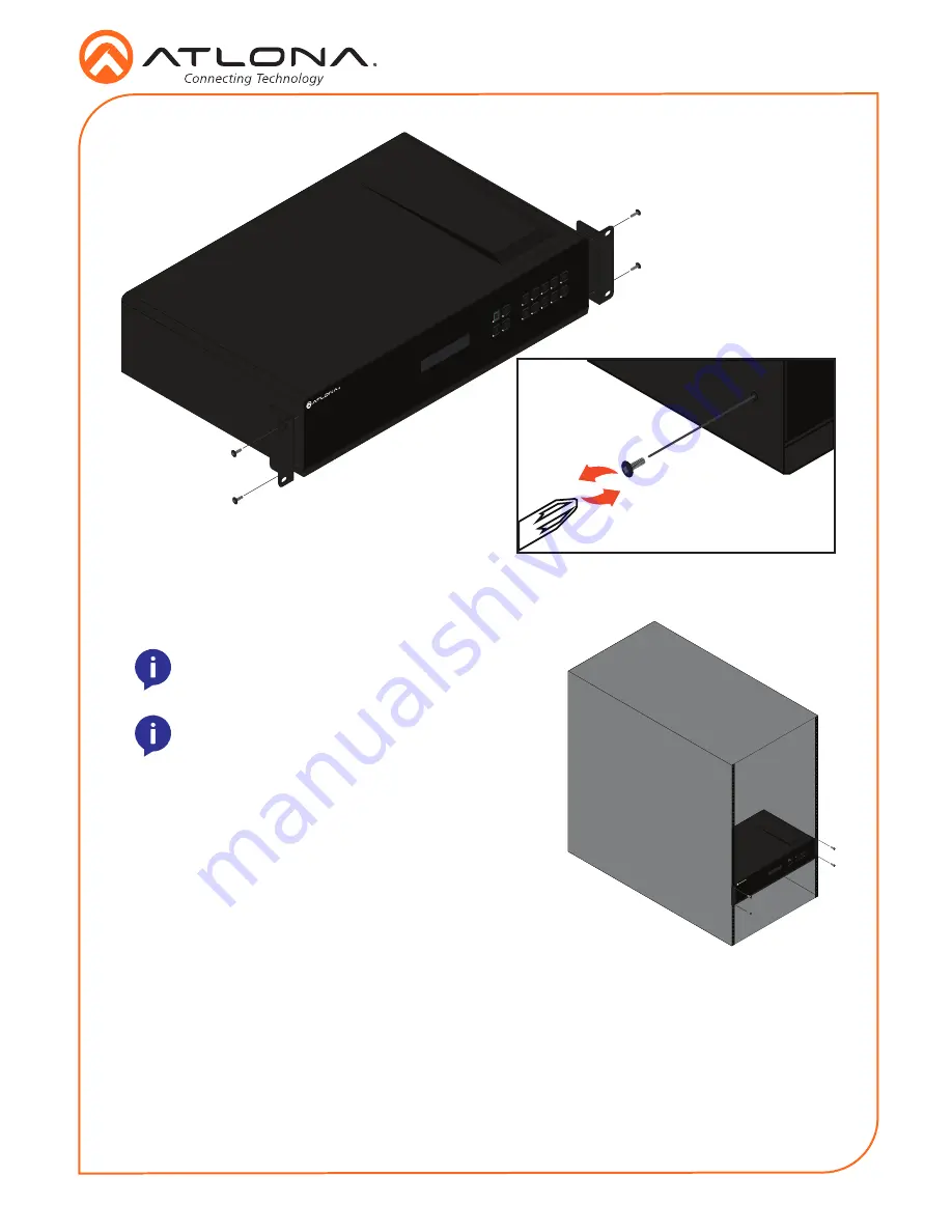
3.  Install the Opus matrix into a rack, using four rack screws.

1

2

3

4

5

6

7

8

1

2

3

4

5

6

7

8

9

10

AUD

IO IN

1

2

1

2

3

4

5

6

7

8

9

10

LAN

DEB

UG

IR IN

RS-2

32

RX

S

TX

R

L

R

L

AUD

IO O

UT

R

L

R

L

R

L

R

L

R

L

R

L

R

L

R

L

R

L

R

L

1

2

TOS

LINK

 IN

3

4

1

2

3

4

5

6

7

8

9

10

TOS

LINK

 OU

T

IR IN

IR O

UT

S

S

S

S

S

S

S

S

S

S

S

S

S

S

S

S

S

S

ON

1

2

3

4

5

6

7

8

1

2

3

4

5

6

PoE

LINK

HDB

aseT

 OU

T

7

8

HDM

I OU

T

9

10

CHA

SSIS

GRO

UND

PoE

LINK

PoE

LINK

PoE

LINK

PoE

LINK

PoE

LINK

PoE

LINK

PoE

LINK

AT-

OPU

S-81

0M

HDM

I IN

AT-

OPU

S-81

0M

CAN

CEL

INFO

EDID

FNC

1

2

3

4

POW

ER

ENT

ER

6

7

8

9

5

10

OPUS

TM

OPUS

TM

Surface mounting

The AT-OPUS-810M can be placed freestanding on top of a desk, a table, or in a cabinet. To 

prevent damage to the surfaces or unnecessary movement of the matrix, four feet have been 

included.
1.  Turn the unit upside down.
2.  Install each foot using the included feet screws, the rubber grips of the feet should be facing 

up during installation.

3.  Turn the unit right-side up and place it in the desired location. 

Summary of Contents for Opus Series

Page 1: ...rates up to 18 Gbps The Opus Series enables flexible routing to HDBaseT outputs plus two additional HDMI outputs and is compatible with the Atlona AT OPUS RX receiver or AT JUNO 451 HDBT switch er for...

Page 2: ...MI IN Connect HDMI cables to these ports from HDMI sources 4 HDBaseT OUT Connect a CAT5e 6 6a 7 cable from this port to an HDBaseT receiver 5 HDMI OUT Connect HDMI cables from these ports to local HDM...

Page 3: ...wire Use with 3rd party control systems For easy termination Atlona recommends using the 2 meter IR cable AT LC CS IR 2M Control RS 232 IR GND S GND RX TX GND RX TX Mounting Instructions The AT OPUS 8...

Page 4: ...into a rack using four rack screws 1 2 3 4 5 6 7 8 1 2 3 4 5 6 7 8 9 10 AU DIOIN 1 2 1 2 3 4 5 6 7 8 9 10 LAN DEBU G IRIN RS 23 2 RX S TX R L R L AU DIOOU T R L R L R L R L R L R L R L R L R L R L 1...

Page 5: ...AN port 10 Optional For IR routing to and from sources and zones connect a control system IR receivers or IR emitters to the IR IN and IR OUT ports 11 Connect the included IEC power cord to the 100 24...

Page 6: ...which allows easy management and control of all features Follow the instructions below to access the webGUI 1 View the IP address of the unit using the front panel OSD Press the FNC button Press butto...

Page 7: ...2 3 4 5 6 7 8 1 2 3 4 5 6 7 8 9 10 AUD IOIN 1 2 1 2 3 4 5 6 7 8 9 10 LAN DEBU G IRIN RS 23 2 RX S TX R L R L AUD IOOUT R L R L R L R L R L R L R L R L R L R L 1 2 TOSL INK IN 3 4 1 2 3 4 5 6 7 8 9 10...

Page 8: ...Atlona Inc All other brand names and trademarks or registered trademarks are the property of their respective owners Pricing specifications and availability subject to change without notice Actual pro...

Reviews: