


AT-OMNI-111 / AT-OMNI-112
26
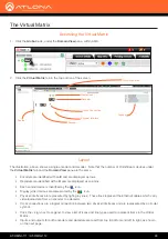
The Virtual Matrix
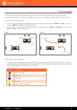
The following example provides a better understanding of how
physical interfaces
and
cross connections
work
together.
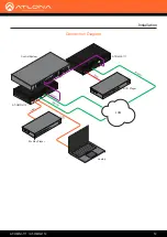
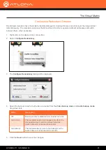
Figure 3
shows a very simple setup: two sources are connected to a dual-channel encoder. Both Ethernet cables
are connected from the encoder to the Local Area Network (LAN). Another set of Ethernet cables connects to a dual-
channel decoder, somewhere on the same network. The Ethernet cables are the
physical interfaces
- that is, they
provide a physical link - that allows the AV stream to be transported, over the network, from an encoder to a decoder
endpoint.
In
Figure 3
, the gray lines indicate that no signal is being sent from the encoder, over the Ethernet cables. Before
a stream can be sent across the network, a
cross connection
must exist between two
physical interfaces
.
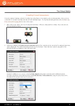
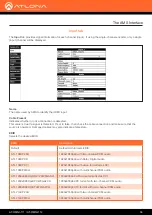
Cross
connections
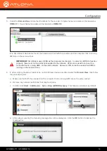
are created under the
Virtual Matrix
tab, in AMS.
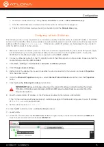
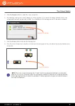
Figure 4a
shows a
cross connection
that joins
Ethernet 1
on the encoder to
Ethernet 1
on the decoder.
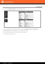
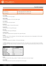
Figure 4b
shows the result of the
cross connection
(green
line) in the setup. Note that the second Ethernet line is still gray, indicating that the cross connection for this physical
interface has not yet been created. Once a cross connection is created, the decoding process starts automatically.
DC 48V
RS-232
ETHERNET
HDMI IN
2
2
1
RX
TX
1
2
+
-
AT-OMNI-112
1
Video
to decoder
to decoder
Video
Ethernet
Ethernet
AT-OMNI-112
Laptop
DVD Player
DC 48V
RS-232
ETHERNET
HDMI IN
AT-OMNI-112
2
2
1
1
RX
TX
1
2
+
-
Video
to decoder
to decoder
Video
Ethernet
Ethernet
OmniStream 112
Encoder
Laptop
DVD Player
Figure 3
Figure 4a
Figure 4b
Cross Connection
Physical Interfaces & Cross Connections


