


AT-OMNI-111 / AT-OMNI-112
24
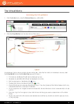
The Virtual Matrix
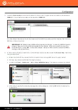
1. Click the
Global
node, under the
Domain View
pane, within AMS.
2. Click the
Virtual Matrix
tab in the top portion of the screen.
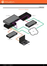
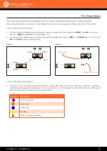
The illustration, above, shows a single encoder and decoder. Note that the number of OmniStream devices under
the
Virtual Matrix
tab and the
Domain View
pane are the same.
•
Encoders are identified with an
E
and are displayed as rows.
•
Decoders are identified with a
D
and are displayed as columns.
•
Each source device is identified by the icon.
•
Display (sink) devices are represented by the icon.
• Physical interfaces
are represented by light-gray lines. These lines represent the Ethernet cables which carry
video/audio data from an encoder to a decoder.
• Cross connections
are a logical connection between two
physical interfaces
and are represented by a circular
symbol.
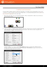
•
Click the + sign, next to Legend, to view a list of icons and line types used to represent items in the Virtual
Matrix.
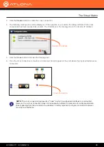
•
Inputs and outputs for both encoders and decoders are read from top to bottom and left to right, as shown
on the next page.
Layout
Accessing the Virtual Matrix
Virtual Matrix tab
Encoder
Source
Legend
Decoder
Display (sink)
Physical Interface
Cross Connection


