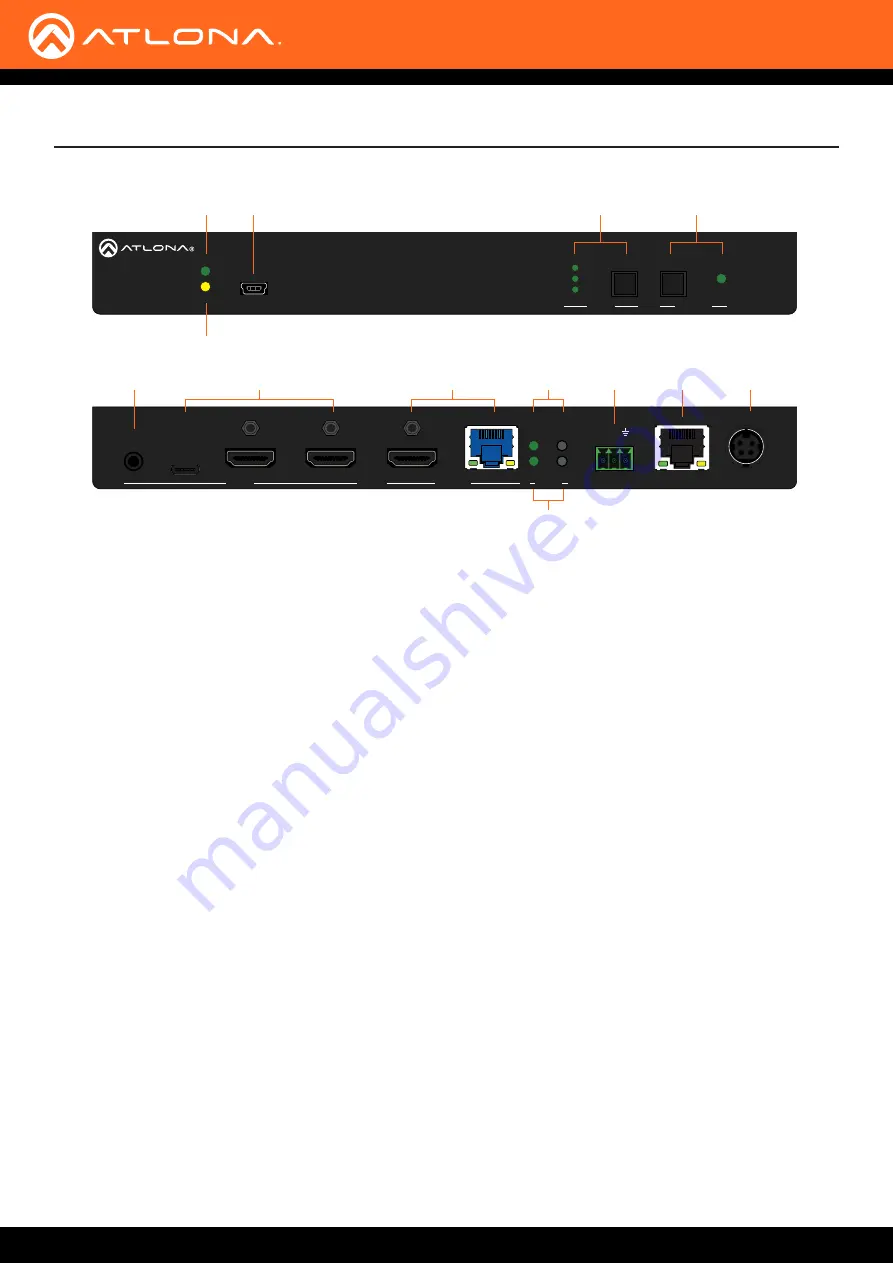
AT-OME-ST31
9
OMEGA
TM
PWR
LINK
FW
1
2
3
INPUT
DISPLAY
AT-OME-ST31
AUDIO
INPUT
1
2
3
AT-OME-ST31
OUTPUT
RESET
IP MODE
RX TX
RS-232
LAN
DC 24V
OMEGA
TM
PWR
LINK
FW
1
2
3
INPUT
DISPLAY
AT-OME-ST31
AUDIO
INPUT
1
2
3
AT-OME-ST31
OUTPUT
RESET
IP MODE
RX TX
RS-232
LAN
DC 24V
1
2
6
7
8
9
10
11
12
13
3
4
5
Front
Rear
Panel
Description
1 PWR Indicator
This LED indicator glows solid green when the unit is
powered.
2 LINK Indicator
This LED indicator glows solid amber when the unit is
being powered remotely, over PoE.
3 FW
Connect a mini-USB cable from this port to update
the firmware. Refer to
for more information.
4 INPUT button
Press and release this button to cycle through each
of the inputs. The LED indicators will display the
currently active input, and correspond to each of the
numbered inputs on the rear panel of the unit.
5 DISPLAY button
Press this button to power-on or power-off the
connected display.
6 AUDIO
Connect a 3.5 mm mini-stereo jack from an analog
audio source to this port. This port provides the
option of replacing the HDMI source audio, and
embedding analog audio on the outputs, using the
web GUI.
7 INPUT ports
Connect a USB-C cable from a video source to
INPUT 1
. Connect HDMI cables to
INPUT 2
and
INPUT 3
from HD/UHD sources.
8 OUTPUT ports
Connect an HDMI from the HDMI port to a display or
other sink device. Connect an Ethernet cable (CAT-
5e or better), from the HDBaseT port to a compatible
HDBaseT receiver. These ports are mirrored.
9 IP MODE
Press and release this button to set the IP mode.
Refer to
information.
10 RESET
Press and release this button to reset the unit to
factory-default settings. Refer to
for more information.
11 RS-232
Connect the included 3-pin captive screw block to
this port. Refer to
for
more information.
12 LAN
Connect an Ethernet cable from this port to the
network.
13 DC 24V
Connect the optional 24 V DC power supply to this
power receptacle.


