background image

AT-OME-ST31

12

IP Configuration

Switching the IP Mode Using the Front Panel

PW LED flashes

Description

Two

Factory Static IP mode (IP address set to 

192.168.1.254

)

Four

DHCP mode

Installation

The AT-OME-ST31 is shipped with DHCP enabled.  Once connected to a network, the DHCP server (if available), 

will automatically assign an IP address to the unit.  If the AT-OME-ST31 is unable to detect a DHCP server within 15 

seconds, then the unit will use a self-assigned IP address within the range of 

169.254.xxx.xxx

.

Use an IP scanner, along with the MAC address on the bottom of the unit, to identify the unit on the network.  

If a static IP address is desired, the unit can be switched to static IP mode.  The default static IP address is 

192.168.1.254

.

1. 

Make sure the AT-OME-ST31 is powered, by connecting an Ethernet cable between a compatible HDBaseT 

receiver, such as the AT-UHD-EX-RX-PSE or AT-HDVS-SC-RX, and the 

HDBaseT 

port on the back of the unit.

2. 

Press and hold the 

IP MODE

 button, on the rear of the unit.

3. 

Release the button once the LED indicator, next to the 

IP MODE

 button, begins to flash green.  The number of 

flashes will indicate the currently selected IP mode.

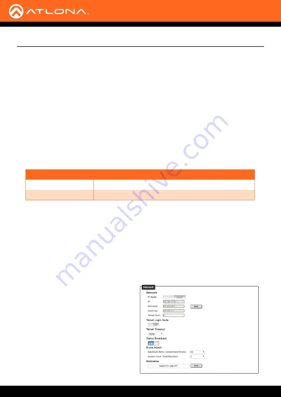
Setting the IP Address using the Web GUI

Refer to the 

System page (page 38)

 in the web GUI, to set the AT-OME-ST31 to either DHCP or static IP mode.  In 

order to access the web GUI, the IP address of the AT-OME-ST31 must be known.  By default, the AT-OME-ST31 is 

set to DHCP mode and will automatically be assigned an IP address by a DHCP server.

1. 

Open the desired web browser and enter the IP address of the AT-OME-ST31.  Refer t

Introduction to the Web 

GUI (page 27)

 for more information.

2. 

Log in, using the required credentials.  The factory-default username and password are listed below.


Username: 

admin


Password: 

Atlona 

3.  Click

 System

 in the menu bar.

4.  Click the 

IP Mode

 toggle and set it to the 

STATIC 

IP

 position.

5. 

Enter the IP address, subnet mask, and gateway 

in the 

IP

Netmask

, and 

Gateway

 fields, 

respectively.

6. 

Click the 

Save

 button, next to the Netmask field, 

to commit all changes.  To undo changes and 

revert to DHCP mode, click the 

IP Mode

 toggle.

Summary of Contents for Omega AT-OME-ST31

Page 1: ...AtlonaManuals Switchers AT OME ST31 Three Input Switcher for HDMI and USB C with HDBaseT and HDMI Outputs 4K UHD ...

Page 2: ...AT OME ST31 2 Version Release Date Notes 1 10 18 Initial release Version Information ...

Page 3: ...voluntary and failure to register will not affect the product warranty To register your product go to http www atlona com registration Sales Marketing and Customer Support Welcome to Atlona Operating Notes IMPORTANT Visit http www atlona com product AT OME ST31 for the latest firmware updates and User Manual Main Office Atlona Incorporated 70 Daggett Drive San Jose CA 95134 United States Office 1 ...

Page 4: ... 10 years from proof of purchase date for hardware electronics products purchased on or after June 1 2013 3 years from proof of purchase date for hardware electronics products purchased before June 1 2013 Lifetime Limited Product Warranty for all cable products NOTE Data cable USB C and Wifi antenna coverd by 1 year warranty Limited Product Warranty Terms Refurbished B Stock Products 3 years from ...

Page 5: ...ts or states do not allow the exclusion or limitation of relief special incidental consequential or indirect damages or the limitation of liability to specified amounts so the above limitations or exclusions may not apply to you Exclusive Remedy To the maximum extent permitted by law this limited product warranty and the remedies set forth above are exclusive and in lieu of all other warranties re...

Page 6: ...5 Do not use this product near water 6 Clean only with a dry cloth 7 Do not block any ventilation openings Install in accordance with the manufacturer s instructions 8 Do not install or place this product near any heat sources such as radiators heat registers stoves or other apparatus including amplifiers that produce heat 9 Do not defeat the safety purpose of a polarized or grounding type plug A ...

Page 7: ...o Output Muting 18 Embedding External Analog Audio 18 Managing Users 20 Adding Users 20 Resetting to Factory Defaults 21 Using the Rear Panel 21 Using the web GUI 21 Advanced Operation 22 RS 232 Control 22 Determining the Port Type 22 Cable Assembly 23 Pass through mode 24 Control mode 26 The Web GUI 27 Introduction to the Web GUI 27 Menu Bar 28 Info 29 A V Settings page 30 Display page 32 RS 232 ...

Page 8: ... an integral component of a fully automated AV system with the convenience of automatic input selection and display control It can be remotely powered by Atlona HDBaseT equipped devices through Power over Ethernet PoE With the optional power supply Part no AT PS 245 D4 the OME ST31 can provide PoE powering to a compatible receiver and also charge laptops and mobile devices through the USB C port F...

Page 9: ...ower off the connected display 6 AUDIO Connect a 3 5 mm mini stereo jack from an analog audio source to this port This port provides the option of replacing the HDMI source audio and embedding analog audio on the outputs using the web GUI 7 INPUT ports Connect a USB C cable from a video source to INPUT 1 Connect HDMI cables to INPUT 2 and INPUT 3 from HD UHD sources 8 OUTPUT ports Connect an HDMI ...

Page 10: ...nected USB C device as well as a PoE receiver The power supply part no AT PS 245 D4 can be purchased from Atlona NOTE The HDMI and HDBaseT OUTPUT ports are mirrored meaning that the same A V signal is transmitted over both ports 5 Connect an Ethernet cable from the LAN port to the Local Area Network This will allow access to the built in web server and provide remote control of the AT OME ST31 Cab...

Page 11: ...am AT UHD EX 100CE RX PSE AT OME ST31 Laptop Laptop Display E t h e r n e t H D M I H D M I U S B C H D B a s e T H D M I H D M I LAN Display DC 48 V RS 23 2 HD Ba seT IN HD MI OU T RX TX OM EG A TM PW R LIN K FW 1 2 3 INP UT TES T AT OM E S T31 ...

Page 12: ... hold the IP MODE button on the rear of the unit 3 Release the button once the LED indicator next to the IP MODE button begins to flash green The number of flashes will indicate the currently selected IP mode Setting the IP Address using the Web GUI Refer to the System page page 38 in the web GUI to set the AT OME ST31 to either DHCP or static IP mode In order to access the web GUI the IP address ...

Page 13: ...text menu 4 Under the Ethernet Properties dialog box select Internet Protocol Version 4 and then click the Properties button 5 Click the Use the following IP address radio button IMPORTANT Before continuing write down the current IP settings in order to restore them later If Obtain an IP address automatically and Obtain DNS server automatically are selected then this step is not required 6 Enter t...

Page 14: ...pply not included or the Ethernet cable connected between the HDBaseT OUTPUT port and a PoE compatible receiver Off Unit is not powered LINK Solid yellow The AT OME ST31 is receiving power remotely from the HDBaseT receiver Off The link integrity between the AT OME ST31 and the HDBaseT receiver is compromised Check the HDBaseT connections and or try a different cable 1 2 3 Solid green The input is...

Page 15: ...ctive input and is indicated by LED indicator 2 on the front panel 2 Press the INPUT button again to switch to INPUT 3 3 Press the INPUT button once more to return to INPUT 1 Manual input switching can also be performed under the A V Settings page page 30 of the web GUI by clicking the Input Selection drop down list and selecting the desired input In addition the x1AVx1 command can also be used Re...

Page 16: ...l switch to the HDMI port If a USB C source is connected then the AT OME ST31 will switch to the USB C port If a source is disconnected then the AT OME ST31 will fallback to port with an active source If all sources are disconnected then the AT OME ST31 will retain the port of the the last connected source Auto Switching Auto switching can also be used to automatically select an input Auto switchi...

Page 17: ...ed 1 Open the desired web browser and enter the IP address of the AT OME ST31 2 Log in as the admin user with the required credentials The factory default username and password for the admin user are listed below Username admin Password Atlona 3 Click A V Settings in the menu bar 4 Click the USBC toggle switch and set it to the OFF position This will instruct the source device to send non HDCP con...

Page 18: ...ed below Username admin Password Atlona 3 Click A V Settings in the menu bar 4 Locate the Audio section 5 Click the toggle switch for the desired output To mute the audio output on the HDBaseT Output click this toggle switch to the OFF position To re enable the audio for that output set the toggle switch to the ON position 1 Open the desired web browser and enter the IP address of the AT OME ST31 ...

Page 19: ...ble between the analog audio source such as a smartphone and the AUDIO port on the AT OME ST31 OMEGATM PWR LINK FW 1 2 3 INPUT DISPLAY AT OME ST31 AUDIO INPUT 1 2 3 AT OME ST31 OUTPUT RESET IP MODE RX TX RS 232 LAN DC 24V AUDIO port NOTE Video must accompany the audio at all times This product does not support audio only free run mode output b Click the toggle switch of the desired input which wil...

Page 20: ...als The factory default username and password for the admin user are listed below Username admin Password Atlona 3 Click the Config tab 4 Click the Add button under the Edit column 5 Enter the desired username and password in the Username Password Edit dialog box 6 Click the Save Change button to commit changes or click the Cancel button to return to the Config page without adding the user Once cr...

Page 21: ... as part of the reset procedure The AT OME ST31 can also be reset through the web GUI Both procedures will be covered in this section OMEGATM PWR LINK FW 1 2 3 INPUT DISPLAY AT OME ST31 AUDIO INPUT 1 2 3 AT OME ST31 OUTPUT RESET IP MODE RX TX RS 232 LAN DC 24V Reset button Resetting to Factory Defaults 1 Launch a web browser and login to the web GUI Refer to Introduction to the Web GUI page 27 for...

Page 22: ... type is unknown then a multimeter can be used to determine whether the port is DTE or DCE Determining the Port Type DTE Pin Descriptions DCE Pin Descriptions Pin Signal Description 1 DCD Data Carrier Detect 2 RxD Receive Data 3 TxD Transmit Data 4 DTR Data Terminal Ready 5 GND Ground Signal 6 DSR Data Set Ready 7 RTS Request to Send 8 CTS Clear to Send 9 RI Ring Indicator Pin Signal Description 1...

Page 23: ... 16 5 mm of insulation from the TxD RxD and GND wires Cable Assembly When connecting a DTE device to a DCE device a straight through cable should be used A straight through cable is wired in such a way that the pins on one side of the cable are connected to the corresponding pins on the opposite side of the cable as shown in the table below However the AT OME ST31 will use only TxD RxD and GND sig...

Page 24: ...IAL 1 IR OUT SER IAL 2 L R DIG ITAL COA X OUT AUD IO OUT AUD IO IN ETH ERN ET 2 3 4 VIDE O OUT 48V DC FAC TOR Y RES ET AT OME ST31 AT UHD 100CE RX Display Control System DC 48V RS 232 HD Bas eT IN HD MI OU T RX TX OM EG A TM PW R LIN K FW 1 2 3 INP UT TES T AT OM E S T31 1 Connect the RS 232 cable between the control system and the AT OME ST31 Refer to Cable Assembly page 51 for instructions on pr...

Page 25: ...ect the proper baud rate data bit parity and stop bit settings for the HDBaseT OUTPUT port These settings must correspond with the RS 232 settings of the display sink device 4 Click the Save button to commit changes 5 Use the following command to send a command to the display sink device where display_command is the command data to send RS232Zone4 display_command 0d 0d carriage return should only ...

Page 26: ...2 3 4 VID EO OU T 48V DC FAC TO RY RES ET Control System AT OME ST31 OM EG A TM PW R LIN K FW 1 2 3 INP UT TEST AT OME S T31 1 Connect the RS 232 cable between the control system and the AT OME ST31 Refer to Cable Assembly page 51 for instructions on preparing the cable 2 Set the baud rate of the computer control system to 115200 If the control system is not set to this baud rate then the AT OME S...

Page 27: ... OME ST31 and the network 2 Launch a web browser and enter the IP address of the unit If the default static IP address is being used enter 192 168 1 254 3 The AT OME ST31 Login page will be displayed Introduction to the Web GUI 4 Type admin using lower case characters in the User field 5 Type Atlona in the Password field This is the default password The password field is case sensitive When the pa...

Page 28: ...een is the menu bar When the mouse is moved over each menu element it will be highlighted in light orange Once the desired menu element is highlighted click the left mouse button to access the settings within the menu In this example clicking A V Settings in the menu bar will display the A V Settings page Menu bar ...

Page 29: ...ning Always make sure to check the AT OME ST31 product page on the Atlona web site for the latest version of firmware On Time d h m s Displays how long the system has been powered since the last reboot reset Active Input The currently selected active input Signal Type The type of input signal Video Format The input resolution of the source device Aspect Aspect ratio of the input signal Color Space...

Page 30: ...he active input Auto Switch Three controls are available under the Auto Switch feature Auto Switch mode Click this toggle to enable or disable auto switching When enabled the AT OME ST31 will automatically switch to the another port if the signal is disrupted on the currently active input The port to be switched to is defined in the Fallback Input drop down list Fallback Input Click this drop down...

Page 31: ...gle to the OFF position to mute the audio on the HDBaseT OUTPUT port The default setting is ON HDMI Output Set this toggle to the OFF position to mute the audio on the HDMI OUTPUT port The default setting is ON USB Type C Input embed Set this toggle to DIGITAL to use the embedded audio on the USB C input Set to ANALOG to use the analog audio from a source connected to the 3 5 mm mini stereo port T...

Page 32: ...mands Atlona only supports displays that use the CEC command structure defined in HDMI 1 2a It is recommended that dealers re quest an evaluation product from Atlona before designing a system using the CEC protocol If this is not possible then other control methods will need to be considered in order to control displays using Atlona products Display Auto Power On Set this toggle to ENABLED to allo...

Page 33: ...econds between when the display is powered on and when the DISPLAY button on the front panel will be locked Range 0 to 300 Control Type Sets the control method for sending commands The following options are available RS 232 IP CEC Feedback Verify Sets the feedback verification state Click the toggle to enable or disable this feature The following options are available The Web GUI Setting Descripti...

Page 34: ...device to be controlled for the required codes Set command Enter the command in this field Feedback Enter the feedback string in this field CR LF Click this drop down list to select the desired end of line characters to be sent Setting Description None No end of line characters included CR Carriage return LF Line feed CR LF Carriage return Line feed Space Space character STX Start of text characte...

Page 35: ...a device such as the AT UHD EX 100CE RX PSE the drop down list boxes will be disabled and the HDBaseT baud rate will be locked at 115200 If the AT OME ST31 is connected to another HDBaseT device such as the AT UHD CLSO 824 each of these drop down list boxes can be set to the baud rate of the HDBaseT RS 232 settings on the corresponding device Click the Save button to accept the settings Refer to R...

Page 36: ... source will not be displayed Selecting the Default EDID will provide the most compaible settings for most displays In addition 8 memory locations are available for storing captured EDID data EDID Saved The AT OME ST31 provides eight memory locations used for storing captured EDID data Click these drop down lists to select and store the external EDID EDID listing 3840x2160 2CH NO HDR Support 1440x...

Page 37: ...s field cannot be changed Save Click this button to save all changes New Password Enter the new password fro the admin username in this field Confirm New Password Verify the new password by retyping it in this field All User Login Settings Username Displays the username Password Displays the password for the associated username Edit Click the Add button in this column to edit the username and pass...

Page 38: ...is field will only be available when the IP Mode is set to Static The default static IP address is 192 168 1 254 Netmask Enter the subnet mask of the AT OME ST31 in this field This field will only be available when the IP Mode is set to Static Save Click this button to save all changes in the Network group Gateway Enter the gateway router address in this field This field will only be available whe...

Page 39: ...p down list to select the lock out time in minutes Hostname Displays the hostname of the AT OME ST31 as it would appear on a network To change the hostname type the new hostname in this field and click the Save button Power Click this toggle to power on or power off the AT OME ST31 Lock Click this toggle to lock or unlock the AT OME ST31 Factory Default Click this button to reset the AT OME ST31 t...

Page 40: ... Web GUI Requirements AT OME ST31 Firmware file Computer running Microsoft Windows 1 Connect an Ethernet cable from the computer containing the firmware to the same network where the AT OME ST31 is connected 2 Go to the System page page 38 in the web GUI Choose File button 3 Click the Choose File button under the Firmware Update section 4 Browse to the location of the firmware file select it and c...

Page 41: ...e firmware port on the AT OME ST31 The unit will be powered by the USB cable Using USB 7 Click the OK button to begin the firmware update process Click the Cancel button to cancel the process 8 After the firmware update process is complete the Login screen will be displayed OMEGATM PWR LINK FW 1 2 3 INPUT DISPLAY AT OME ST31 AUDIO INPUT 1 2 3 AT OME ST31 OUTPUT RESET IP MODE RX TX RS 232 LAN DC 24...

Page 42: ...ally select the USB UPDATE drive from Windows Explorer 4 Delete all files from the USB UPDATE drive if any are present 5 Drag and drop the firmware file to the drive 6 After the file has been copied disconnect the USB cable from both the computer and the AT OME ST31 7 The firmware update process is complete ...

Page 43: ...t embed HDMI1 Input embed HDMI2 Input embed HDMI1 ON Previous 5 ON ON ON USBC HDMI1 HDMI2 ON ON DIGITAL DIGITAL DIGITAL Display Display Auto Power On Display Auto Power Off Lamp cool down timer Auto power off timer Power on delay timer Control Type Feedback Verify IP Mode IP Address Port Username Password Send Mode Disabled Disabled 5 Seconds 15 Seconds 5 Seconds RS 232 ON Non Login 192 168 1 1 23...

Page 44: ...ystem IP Mode IP Netmask Gateway Telnet Port Telnet Login Mode Telnet Timeout Status Broadcast Maximum Retry Connection System Lock Time Hostname Power Lock DHCP 192 168 1 254 255 255 255 0 192 168 1 1 23 OFF 10000 ON 10 tries 3 minutes OMEST31 000xxx ON Unlock ...

Page 45: ...ounting brackets 1 Using a small Phillips screwdriver remove the two screws from the left side of the enclosure OMEGA TM PWR LINK FW 1 2 3 INPUT TEST AT OME ST31 OMEGA TM PWR LINK FW 1 2 3 INPUT TEST AT OME ST31 2 Position one of the mounting brackets as shown below aligning the holes on the side of the enclosure with one set of holes on the mounting bracket 3 Use the screws from Step 1 to attach ...

Page 46: ...the second mounting bracket to the opposite side of the unit 5 Mount the unit to a flat surface using the oval shaped holes on each mounting bracket If using a drywall surface a 6 drywall screw is recommended OMEGA TM PWR LINK FW 1 2 3 INPUT TEST AT OME ST31 ...

Page 47: ... 60 59 94 50Hz 720p 60 59 94 50Hz 576p 50Hz 576i 50Hz 480p 60 59 96Hz 480i 60Hz VESA 2560 1600 2048 1536 1920 1200 1680 1050 1600 1200 1440 900 1400 1050 1280 1024 1280 800 1366 768 1360 768 1152 864 1024 768 800 600 640 480 USB C Up to 4K UHD 60Hz Color Space YUV RGB Chroma Subsampling 4 4 4 4 2 2 4 2 0 Color Depth 8 bit 10 bit 12 bit HDR HDR10 Hybrid Log Gamma HLG and Dolby Vision 60Hz HDMI inpu...

Page 48: ...tocols DHCP HTTP Telnet Ethernet Speed 10 100 Mbps Addressing DHCP static Temperature Fahrenheit Celsius Operating 32 to 113 0 to 45 Storage 4 to 140 20 to 60 Humidity RH 20 to 60 non condensing Power Total power consumption Type C System consumption Idle PSE 77 52 W 60 W 9 68 W 8 1 W 9 42 W Supply Input 100 240 V AC 50 60 Hz Output 24 V 6 25 A DC Dimensions Inches Millimeters H x W x D 1 02 x 8 6...

Page 49: ...ex 49 Input switching automatic 16 manual 15 IP configuration 12 auto IP 13 IP address default 38 setting 38 M Mounting instructions 45 O Operating notes 3 P Panel descriptions 9 Password setting 37 R Reset factory default 39 RS 232 cable assembly 23 control mode 26 pass through mode 24 S Safety information 6 Settings default 43 Specifications 47 Subnet mask setting 38 Switching auto 16 manual 15 ...

Page 50: ... registered trademarks of Atlona Inc All other brand names and trademarks or registered trademarks are the property of their respective owners Pricing specifications and availability subject to change without notice Actual products product images and online product images may vary from images shown here ...

Reviews: