


2
Installation Guide
AT-OME-EX-KIT
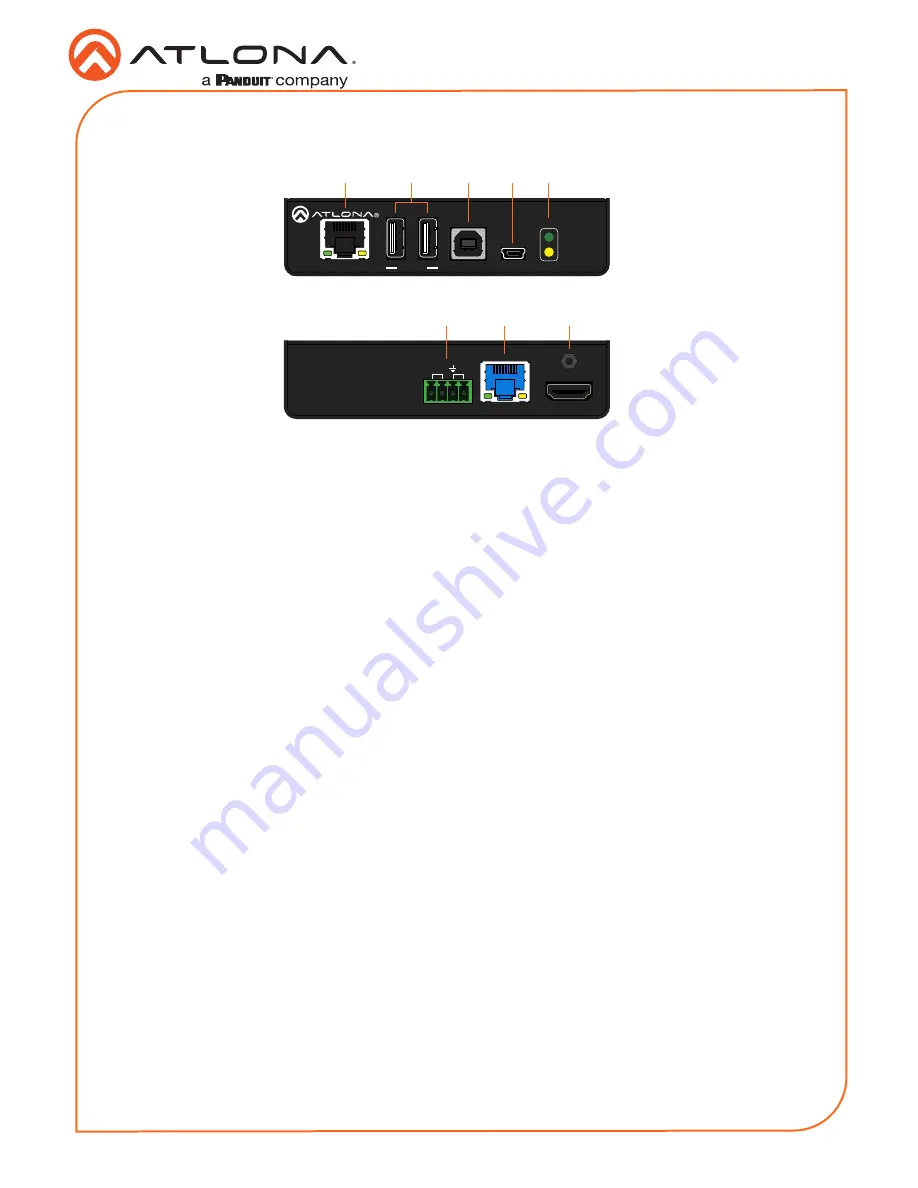
1
LAN
Connect a category cable from this port to a network switch. This cable provide IP pass-
through transport control from a control system to the display (sink) device connected to the
receiver.
2
DEVICE
Connect up to two USB devices (e.g. mouse, keyboard, etc.) to these ports. Each port
provides 5 V / 500 mA.
3
HOST
Connect a USB cable from this port to the host computer.
4
FW
Connect a mini USB-to-USB cable from this port, to a computer, to update the firmware.
Refer to
Updating the Firmware (page 10)
for more information.
5
PWR / LINK
The
PWR
LED indicator will glow green when the AT-OME-EX-TX is powered. The AT-OME-
EX-RX supplies power to the AT-OME-EX-TX over HDBaseT. The
LINK
LED indicator glows
yellow when a solid link is established between the transmitter and receiver. Refer to
LED
Indicators (page 7)
for more information.
6
RS-232 / IR
Connect the included 4-pin captive screw block to this receptacle. Refer to
RS-232 and IR
(page 4)
for more information.
7
HDBaseT OUT
Connect a category cable from this port to the
HDBaseT IN
port of the AT-OME-EX-RX or
other PoE-compatible receiver.
8
HDMI IN
Connect an HDMI cable from this port to the source device.
Front
Rear
LAN
HDBaseT IN
DC 48V
AT-OME-EX-RX
HDMI OUT
RX
TX
TX
RS-232 IR
LAN
FW
HOST
OMEGA
TM
DEVICE
PWR
LINK
AT-OME-EX-RX
FW
PWR
LINK
OMEGA
TM
DEVICE
HDMI IN
AT-OME-EX-TX
HDBaseT OUT
RX
RX
TX
RS-232 IR
8
6
7
LAN
HDBaseT IN
DC 48V
AT-OME-EX-RX
HDMI OUT
RX
TX
TX
RS-232 IR
LAN
FW
HOST
OMEGA
TM
DEVICE
PWR
LINK
AT-OME-EX-RX
FW
PWR
LINK
OMEGA
TM
DEVICE
HDMI IN
AT-OME-EX-TX
HDBaseT OUT
RX
RX
TX
RS-232 IR
2
1
3
4
5
AT-OME-EX-TX


