3
Installation Guide
AT-HDVS-210H-TX-WP
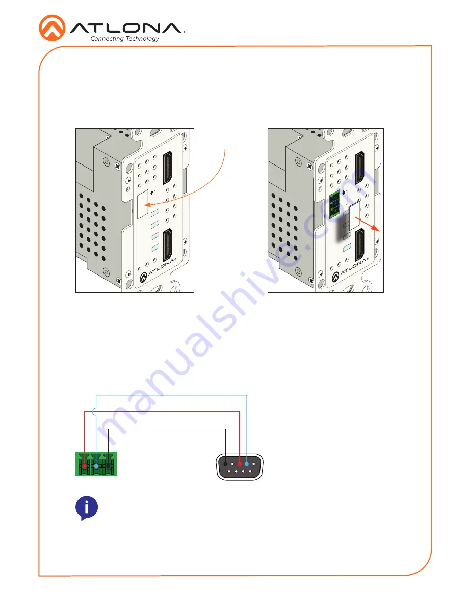
The AT-HDVS-210H-TX-WP provides an
RS-232
port which allows communication between a
control system and an RS-232 device. This step is optional.
1. Remove the small plate covering the RS-232 port on the faceplate.
2. Use wire strippers to remove a portion of the RS-232 cable jacket.
3. Remove at least 3/16” (5 mm) from the insulation of the RX, TX, and GND wires.
4. Insert the TX, RX, and GND wires into correct terminal using the included 3-pin captive
screw connector.
5. Connect the opposite end of the cable to the control system.
NOTE:
Typical DB9 connectors use pin 2 for TX, pin 3 for RX, and pin 5 for
ground. On some devices functions of pins 2 and 3 are reversed.
RS-232
GND
RX
TX
HDMI 2
LINK
HDMI 1
HDMI 2
PWR
RS-232
RX
TX
HDMI1
AT-HDVS-210H-TX-WP
HDMI 2
LINK
HDMI 1
HDMI 2
PWR
RS-232
RX
TX
HDMI1
AT-HDVS-210H-TX-WP
small plate


