2920 7090 00
57
Instruction book
Ref Description
A
Control air to unloader
R
Vent hole
1
Unloading handle
2
Pressure adjusting screw
3
Nuts
4
Shims
Unload mechanism
The pilot valve is equipped with a hand-operated unload mechanism: by turning the red handle (1) 90
degrees, the plunger of the valve will be lifted, releasing the spring force. The air pressure from
the
pulsation dampers will force down unloader plunger (8) and the compressor will run unloaded.
By
turning handle (1) 90 degrees further, the plunger returns to its original position so that the pilot
valve
will again unload and load the compressor at the pre-set pressures.
Setting of the pilot valve
The maximum pressure is controlled by adjusting screw (2):
1.
Loosen handle (1) and the two nuts (3)
2.
Turn the adjusting screw (2) clockwise to increase the maximum pressure.
3.
The pressure difference can be increased by removing one or more shims (4).
4.
Fit the two nuts (3) and handle (1) in their original position.
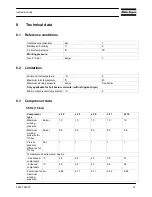
6.7 Safety
valve
Replace the valve if it does not open at the correct pressure. No adjustment is
allowed.
Testing:
Testing as described below shall only be carried out by competent
personnel.
If safety valve is not used for longer than 6 months, pressurize for 4h to have working
pressure
If safety valve is not used for longer than 6 months, pressurize for 4h to have working pressure
Testing
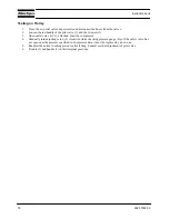
1.
Close the air outlet valve, depressurize and disconnect the hose or pipe from the valve
2.
Start the compressor and run it until it stops automatically.
3.
Switch off the voltage.
Remove the cover from the air pressure switch and, with the air receiver now under pressure, turn the
adjusting screw one turn clockwise to increase the stopping pressure Adjustment of MDR4S pressure switch
and Adjustment of MRD3 pressure switch. Reinstall the cover.
4.
Switch on the voltage, slightly open the outlet valve and start the compressor
5.
Gradually close the outlet valve while checking the air pressure gauge. If the safety valve has not opened at
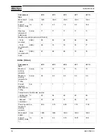
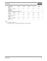
the pressure specified in Compressor data, it must be replaced by a new one. If the compressor unloads
before the specified opening pressure is reached, repeat the procedure as mentioned from step 3.
6.
Readjust the unloading pressure as described in sections Adjustment of MDR4S pressure switch and
Adjustment of MRD3 pressure switch
7.
Reconnect the hose or pipe to the closed air outlet valve
Summary of Contents for LF 10
Page 1: ...Atlas Copco Industrial aluminium piston compressor LF 2 LF 3 LF 5 LF 7 LF 10 Instruction book ...
Page 2: ......
Page 12: ...10 2920 7090 00 Instruction book Power Pack with unloading valve Base mounted ...
Page 18: ...16 2920 7090 00 Instruction book Air flow and regulating system with DOL starter ...
Page 19: ...2920 7090 00 17 Instruction book Air flow and regulating system with Y D starter ...
Page 20: ...18 2920 7090 00 Instruction book Air flow and regulating system of trolley ...
Page 72: ......
Page 73: ......
Page 74: ......


