22
2920 7090 00
Instruction book
3 Installation
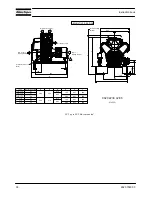
3.1 Dimension
drawings
Dimension drawings
B
B
A
4
9
6
4
0
For Dismantling
Air filter
254
202
X
VIEW F
G-G
Cooling Air Inlet
Compressor Air Inlet
LE/LF/LT 2-3:WITHOUT VIBRATION DAMPER
LE/LF/LT 5 :WITH VIBRATION DAMPER
G
G
112
20
1
5
7
1
0
0
91
30
141
368
Compressed Air outlet
G1/2"
26
1
6
7
P
it
c
h
Ø
1
5
4
H
7
Ø
2
1
8 p9
Ø
5
k
5
2
M8(4x)
VIEW F
M10
N e t M a s s
B l o c k ( K g )
N e t M a s s P o w e r
p a c k ( K g )
A
B
C
D
E
5
4
2
6 1 5
9
4
3
1
5
5
5
4
2
6 1 5
9
4
3
1
5
5
T y p e
5 0 4
2 5 2
L T
3 0
3 0
5 3 3
2 7 9
L E / L F
3 6 5
7 7
6 8 7
6 8 7
Cooling Air Inlet
Cooling
Air inlet
1
5
7
615
Compressed Air outlet
G1/2"
26
74
0,5
1
6
7
5
0
6
E
C
4
0
For dismantling
Air filter
7
1
Compressed Air Outlet
G1/2"
VIEW H
VIEW H
D
Y
Z
9820 2239 01/08
81448D
LF 2 up to LF 5, Power Pack
Summary of Contents for LF 10
Page 1: ...Atlas Copco Industrial aluminium piston compressor LF 2 LF 3 LF 5 LF 7 LF 10 Instruction book ...
Page 2: ......
Page 12: ...10 2920 7090 00 Instruction book Power Pack with unloading valve Base mounted ...
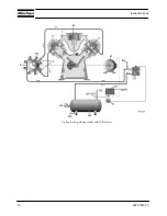
Page 18: ...16 2920 7090 00 Instruction book Air flow and regulating system with DOL starter ...
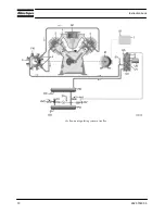
Page 19: ...2920 7090 00 17 Instruction book Air flow and regulating system with Y D starter ...
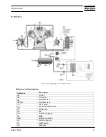
Page 20: ...18 2920 7090 00 Instruction book Air flow and regulating system of trolley ...
Page 72: ......
Page 73: ......
Page 74: ......


