Atlas Copco ER S-1 Instruction Book Download Page 23


20/06/2011 

PM 9845 0512 02 


Page 21 of 36 

7.  Operation  

7.1.  Thermostatic bypass valve 

Heat exchanger bypass valve (of ER unit) with lever 
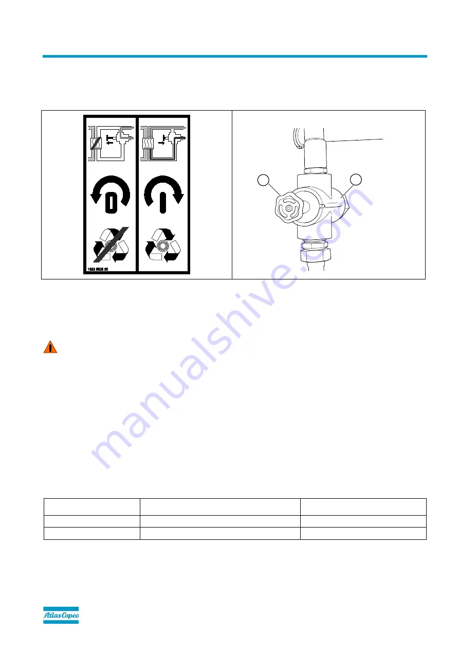
Figure 13: ER label 

Figure 14: Thermostatic valve housing ER kit 


The 1st bypass valve of the ER (Figure 14-7) is provided with a special lever (Figure 14-26). This lever controls the 
operation of the energy recovery system.  
As can be seen on the ER label (Figure 13), the ER unit is integrated in the oil circuit and recovers energy when the lever is 
turned in fully clockwise.  
When the lever is turned out fully counter clockwise, the ER unit is bypassed in the oil circuit and does not recover energy.  


Always turn the lever (Figure 14-26) all the way in or out. Do not position it anywhere in between both ends.


Main oil cooler bypass valve of oil filter pipe 

The 2nd bypass valve (Figure 2-14) starts closing the bypass line and opening the oil supply line from the main oil cooler 
(Figure 2-23) at the lower limit of its temperature range; at the upper limit of its temperature range, the bypass line is 
completely closed and all the oil flows through the main oil cooler.  

On all compressors (fixed speed and VSD compressors), a thermostat with a higher temperature range (compared to the 
standard thermostat) is required in the 2nd bypass valve of the oil filter pipe when using the compression heat as its source 
for energy recovery. 


Thermostatic valve instructions 

The  thermostatic  valve of the compressor must  always open at least 10°C later than the one in the ER unit to prevent 
tripping of the valves. See table for actions: 

Valve of Compressor 

Action on Compressor 

Action on ER unit 

40 °C 

Replace valve with 60 °C 

Place valve 40 °C 

60 °C 

Replace valve with 75 °C 

Place valve 60 °C 


26 


Summary of Contents for ER S-1

Page 1: ...Atlas Copco Energy Recovery Stand Alone Kit Instruction book ...

Page 2: ......

Page 3: ...stallation 4 General precautions 4 Precautions during installation 4 4 2 Safety precautions during operation 5 General precautions 5 Precautions during operation 5 4 3 Safety precautions during maintenance or repair 6 General precautions 6 Precautions during maintenance or repair 6 5 Energy Recovery ER 8 5 1 Description 8 5 2 Components 8 5 3 Labels 8 5 4 Main parts of the Energy Recovery unit 10 ...

Page 4: ... too low 22 7 3 Energy recovery system is turned off 23 7 4 Commissioning the energy recovery system 23 For fixed speed compressors 23 For VSD compressors 23 7 5 Stopping the ER unit for a longer period 23 8 Maintenance 24 8 1 Compressor oil 24 Before installation 24 Oil filling instructions 24 Oil drain instructions 24 Volumes 25 Length flexibles 25 8 2 Thermostatic bypass valves 25 8 3 Heat exch...

Page 5: ...2 29 37 75 kW VSD range ER S 2 29 55 90 kW VSD range ER S 3 29 90 180 kW VSD range ER S 4 29 180 315 kW range ER S 5 29 9 9 Pressure drop heat exchangers 30 Formulas 30 9 10 Dimension drawings 31 9 11 Installation proposal 34 9 12 Conversion list of metric units into imperial units 34 10 Circuit diagrams 9845 1800 00 35 10 1 ER Mk 4 Elektronikon 35 10 2 ER Mk 5 Elektronikon 36 ...

Page 6: ... must be opened and locked 6 Never play with compressed air Do not apply the air to your skin or direct an air stream at people Never use the air to clean dirt from your clothes When using the air to clean equipment do so with extreme caution and wear eye protection 7 The owner is responsible for maintaining the unit in safe operating condition Parts and accessories shall be replaced if unsuitable...

Page 7: ... General precautions 1 The operator must employ safe working practices and observe all related work safety requirements and regulations 2 If any of the following statements does not comply with the applicable legislation the stricter of the two shall apply 3 Installation operation maintenance and repair work must only be performed by authorised trained specialised personnel 4 The compressor is not...

Page 8: ...hes When using the air to clean equipment do so with extreme caution and wear eye protection Precautions during maintenance or repair 1 Always wear safety glasses 2 Use only the correct tools for maintenance and repair work 3 Use only genuine spare parts 4 All maintenance work shall only be undertaken when the machine has cooled down 5 A warning sign bearing a legend such as work in progress do no...

Page 9: ...bration dampers e g damping material on the bodywork and in the air inlet and outlet systems of the compressor is in good condition If damaged replace it by genuine material from the manufacturer to prevent the sound pressure level from increasing 20 Never use caustic solvents which can damage materials of the air net e g polycarbonate bowls 21 The following safety precautions are stressed when ha...

Page 10: ...nless steel oil water heat exchanger Thermostatic bypass valve with on off lever Temperature sensors for water inlet and outlet control Necessary bolts pipes hose assemblies etc The Energy Recovery system also includes thermostats for both the bypass valve of the Energy Recovery unit and the main bypass valve of the oil filter pipe Flexibles to connect the kit to the main compressor Tap flange exc...

Page 11: ...e 9 of 36 1079 9912 28 Oil out 1079 9930 01 Oil in 1630 0267 00 System remark 0690 1116 01 Atlas Copco logo 1630 0264 00 ER S 1 logo 1630 0265 00 ER S 2 logo 1630 0266 00 ER S 3 logo 1630 0349 00 ER S 4 logo 1630 0350 00 ER S 5 logo ...

Page 12: ...ction 6 Oil outlet connection 7 1 st bypass valve with thermostat and lever for manual on off control of the ER unit 8 Heat exchanger or ER unit 9 Oil flexible oil outlet 10 Venting nipple The functions of the main components are detailed below in this manual The size of the heat exchanger varies according to its range The 55 90 kW range heat exchanger is shown in the figure above The set up is si...

Page 13: ...ter of oil filter pipe 25 Compressor element The 1st bypass valve Figure 2 7 is integrated in the ER unit and controls the operation of the oil heat exchanger Figure 2 8 of the ER unit The 2nd bypass valve Figure 2 14 is integrated in the oil filter pipe and controls the operation of the main oil cooler Figure 2 23 of the compressor Both bypass valves consist of an insert thermostat mounted in a h...

Page 14: ...filter pipe oil filter housing 11 Oil drain 12 Oil separator vessel 13 Oil filter pipe with 2 nd bypass valve and oil filter housing 14 2 nd bypass valve BV2 of filter pipe 15 Oil flexible from vessel to oil inlet connection of ER unit 16 Oil flexible from oil outlet connection of ER unit to oil filter pipe 19 Wiring for oil temperature sensors 2 off To enable the energy recovery unit to be insert...

Page 15: ...d bypass valve BV2 of filter pipe 15 Oil flexible from vessel to oil inlet connection of ER unit 16 Oil flexible from oil outlet connection of ER unit to oil filter pipe To allow the energy recovery unit to be inserted into the compressor oil circuit the oil pipe Figure 4 10 between the oil separator vessel Figure 4 12 and the oil filter housing Figure 4 13 must be removed This pipe will NOT be re...

Page 16: ...compressor oil circuit a special tap flange Figure 5 17 and 2 spacers Figure 5 18 must be installed between the oil separator vessel Figure 5 12 and the oil filter pipe Figure 5 13 This flange allows the oil to be drained out of the oil separator vessel Figure 5 12 and directly into the oil inlet connection Figure 7 5 of the ER unit using a flexible Figure 5 15 Connect the other flexible Figure 5 ...

Page 17: ...ection panel A flexible Figure 3 4 5 15 connects the outlet of the oil separator vessel Figure 3 4 5 12 and the oil inlet connection Figure 7 5 The oil outlet connection Figure 7 6 is connected to the bottom of the oil filter housing Figure 3 4 5 13 through a second flexible hose Figure 3 4 5 16 This is the original connection of the oil pipe Figure 3 4 10 The ER unit should be placed as near as p...

Page 18: ... 02 Page 16 of 36 Figure 9 View on rubber grommets in side panel Install 3 split grommets in the drilled holes to prevent the flexible hoses 2x and the conduit gland 1x from getting damaged by burrs in the holes see Figure 9 ...

Page 19: ...t be determined on site 30 315 kW VSD NOTE 90 315 kW is only available with Mk 4 controller Figure 10 Electrical modifications to install the ER unit with Mk 4 Figure 11 Electrical modifications to install the ER unit with Mk 5 4 Temperature sensor cables 5 Expansion module 6 Link cable 7 Main controller module Elektronikon The two temperature sensors Figure 1 3 4 are connected using sensor cables...

Page 20: ...this may damage the electronic parts in the cubicle It is recommended to make a hole of ø 26 mm with a special punch tool no drilling is required For details about the electrical installation of this expansion module please refer to the service diagram supplied with the main compressor 5 8 Remarks The ER unit is delivered as a complete kit The said mechanical and electrical modifications must be c...

Page 21: ...ate Example Calculation see An open circuit with cold water from a main supply being heated by the energy recovery system for use in a factory e g preheating boiler feed water chapter 9 6 6 4 Recovery water flow The recovery water enters the ER unit at the water inlet connection Figure 1 1 In the heat exchanger Figure 1 8 the compression heat is transferred from the compressor oil to the water The...

Page 22: ...control To minimize these problems the water should meet a number of requirements Please contact Atlas Copco in case of doubt Recommended maxima mg l Closed water circuit Open water circuit Chloride Cl 600 150 Sulphate SO4 400 250 Total solids 3000 750 Suspended solids as SiO2 10 10 Free chlorine Cl2 4 2 Ammonia NH4 0 5 0 5 Copper 0 5 0 5 Iron 0 2 0 2 Manganese 0 1 0 1 Oxygen 3 3 Carbonate hardnes...

Page 23: ...bypass valve of oil filter pipe The 2nd bypass valve Figure 2 14 starts closing the bypass line and opening the oil supply line from the main oil cooler Figure 2 23 at the lower limit of its temperature range at the upper limit of its temperature range the bypass line is completely closed and all the oil flows through the main oil cooler On all compressors fixed speed and VSD compressors a thermos...

Page 24: ...ugh the heat exchanger The oil from the heat exchanger outlet flows via the oil filter Figure 2 24 the compressor element Figure 2 25 and the separator Figure 2 12 back to the inlet of the heat exchanger The 2nd bypass valve Figure 2 14 continues to bypass the main oil cooler Figure 2 23 as long as the oil temperature after the heat exchanger Figure 2 8 remains below 75 C The heat exchange between...

Page 25: ... exceptional e g in case of maintenance of the water circuit of the energy recovery unit or if no energy is required for a longer period 7 4 Commissioning the energy recovery system For fixed speed compressors Run the unit unloaded for a few minutes before switching on off the energy recovery unit by turning the lever fully in out Figure 14 26 For VSD compressors Close the air outlet valve and run...

Page 26: ...gy Recovery Unit is closed 4 Repeat the instructions in the section Oil and filter change of the instruction manual of the main compressor Do not run the compressor on warm too long Installation of Energy recovery Unit increases the minimum oil volume Running on warm for long time will damage your compressor When using Food Grade oil decrease the oil exchange interval to 3000 working hours Oil dra...

Page 27: ...re rise over the energy recovery system declines over a period of time with the same basic working conditions the heat exchanger Figure 1 8 should be inspected To clean the oil side soak the heat exchanger in a degreasing solution To remove scale formation in the water compartment a proper de scaling process should be applied Please contact Atlas Copco 8 4 Maintenance schedule INSPECTION VISIT A V...

Page 28: ...er inlet temperature of the ER unit The water outlet temperature of the ER unit 9 5 Modifying settings If the pre programmed warning settings for the water temperatures are exceeded a warning indication is shown on the compressor control module Temperature input Unit Min setting Nom setting Max setting Energy recovery water inlet C 0 50 99 Delay at warning signal sec 0 Please contact Atlas Copco 2...

Page 29: ...w typical values are provided for the above mentioned type of water flow system 11 30 kW range VSD ER S 1 Parameters Units 11 kW 15 kW 18 kW 22 kW 26 kW 30 kW Recoverable energy kW 8 3 11 3 13 5 16 5 19 5 22 5 Water flow l min 11 8 16 1 19 3 23 6 27 9 32 2 Temperature at inlet ºC 50 50 50 50 50 50 Temperature at outlet ºC 60 60 60 60 60 60 Pressure drop bar 0 008 0 014 0 019 0 027 0 037 0 048 30 4...

Page 30: ...S 5 Parameters Units 200 kW 250 kW 315 kW Recoverable energy kW 150 0 187 5 236 3 Water flow l Min 214 3 267 9 337 5 Temperature at inlet C 50 50 50 Temperature at outlet C 60 60 60 Pressure drop bar 0 680 1 021 1 554 9 8 Data for high temperature rise low water flow systems NOTE Please remember that this type of application can adversely affect compressor performance Please refer to section 6 4 f...

Page 31: ... parameters units 55 kW 75 kW VSD 90 kW VSD Recoverable energy kW 41 3 56 3 67 5 Water flow l Min 8 3 11 4 13 6 Temperature at inlet C 20 20 20 Temperature at outlet C 91 91 91 Pressure drop bar 0 004 0 007 0 010 90 180 kW VSD range ER S 4 Parameters Units 90 kW 110 kW VSD 132 kW VSD 160 kW VSD 180 kW VSD Recoverable energy kW 67 5 82 5 99 0 120 0 135 0 Water flow l min 13 5 16 6 20 0 24 2 27 2 Te...

Page 32: ...45 0512 02 Page 30 of 36 9 9 Pressure drop heat exchangers Figure 15 graph Formulas ER S 1 Pd 0 15034 Q 1 8581 ER S 2 Pd 0 41764 Q 1 8906 ER S 3 Pd 0 08487 Q 1 8983 ER S 4 Pd 0 10198 Q 1 8437 ER S 5 Pd 0 06673 Q 1 8225 ...

Page 33: ...20 06 2011 PM 9845 0512 02 Page 31 of 36 9 10 Dimension drawings 9845 0069 00 11 30 kW 9845 0070 00 30 45 kW 9845 0071 00 55 90 kW 9845 0124 00 90 180 kW 9845 0125 00 180 315 kW Figure 16 9845 0069 00 ...

Page 34: ...20 06 2011 PM 9845 0512 02 Page 32 of 36 Figure 17 9845 0070 00 Figure 18 9845 0071 00 ...

Page 35: ...20 06 2011 PM 9845 0512 02 Page 33 of 36 Figure 19 9845 0124 00 Figure 20 9845 0125 00 ...

Page 36: ...tion proposal Installation Proposal please refer to document 9845 0133 00 on GBP or contact your official Atlas Copco Service Specialist 9 12 Conversion list of metric units into imperial units 1 bar 14 504 psi 1 l min 0 035 cfm 1 kW 1 341 hp x C 32 1 8x F ...

Page 37: ...20 06 2011 PM 9845 0512 02 Page 35 of 36 10 Circuit diagrams 9845 1800 00 10 1 ER Mk 4 Elektronikon Figure 21 Reference Designation E2 Expansion module TT53 ER water in TT54 ER water out ...

Page 38: ...20 06 2011 PM 9845 0512 02 Page 36 of 36 10 2 ER Mk 5 Elektronikon Figure 22 Reference Designation E2 Expansion module TT53 ER water in TT54 ER water out ...

Page 39: ......

Page 40: ...PM 9845 0512 02 2011 06 Printed in Belgium www atlascopco com ...

Reviews: