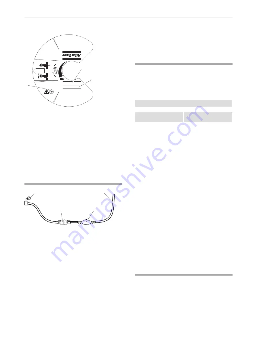
Safety label
XXX XX
Co
nst
ruc
tio
n T
oo
ls AB
Atla
s C
op
co
NA
CK
A- SWE
DEN
Desi
gned
b
y
Ordering No
XXXX XXXX XX
Type
Pmax bar(e)
XXX XX
20 (290psi)
FLOW
MAX
MI
N
A
B
C
A.
Machine type
B.
Maximum permitted compressed air pressure
C.
The warning symbol together with the book
symbol means that the user must read the
safety and operating instructions before the
machine is used for the first time.
Installation
Hoses and connections
A
B
C
D
A.
Compressed air source
B.
Water separator (optional)
C.
Lubricator
D.
Max. 3 m (10 ft) compressed air hose between
the lubricator and the pneumatic machine.
♦
The maximum permissible air pressure, 20 bar (e)
(290 psi), must not be exceeded.
♦
Blow any impurities out of the compressed air hose
before connecting it to the lubricator.
♦
For the CLG 10 a hose with a minimum internal
diameter of 12.5-16.0 mm (
1
⁄
2
-
5
⁄
8
in.) must be used.
For the CLG 30 a hose with a minimum internal
diameter of 20-25 mm (
3
⁄
4
-1 in.) must be used.
♦
There is a an arrow on the lubricator to indicate
the correct direction of air flow. When connecting
the lubricator, make sure that the arrow points in
the same direction as the air flow.
Lubrication
The lubricant is important for the pneumatic
machine’s function and has a great impact on the
useful service life. To guarantee good lubrication,
the length of the air hose between the lubricator and
the pneumatic machine must not exceed 3 meters.
Viscosity range
Viscosity
Temperature °C (°F)
ISO VG 46–68
200-300 SUS
+15 to +50
(+59 to +122)
ISO VG 22–32
100-150 SUS
-20 to +15
(-4 to +59)
For the correct recommended lubrication oil, refer to
the Safety and operating instruction for the pneumatic
machine used together with the lubricator.
Oil adjustment
CLG 10 and 30 are delivered with the oil dosage
screw in the fully open position. The oil dosage screw
can be turned through a total of four complete turns.
It is steplessly adjustable.
To adjust the oil dosage, do the following:
♦
Use a screwdriver to turn the oil dosage screw.
Clockwise reduces oil flow.
Anticlockwise increases oil flow.
♦
Never remove the spring pin. If the oil dosage
screw become loose, the spring pin will prevent it
from blowing out of the lubricator.
♦
Check the exhaust port of the pneumatic machine
to see that sufficent lubrication is being exhausted.
Operation
Operating
Filling the lubricator with oil
Always top up the lubricator with oil at the start of
the shift.
♦
Switch off the air supply to the lubricator.
♦
Vent the air line, to remove trapped air.
♦
Clean around the outside of the filler plug to
prevent dirt from entering the lubricator.
9
© 2015 Construction Tools PC AB | No. 9800 1172 01a | 2015-04-10
Original instructions
Safety and operating instructions
CLG 10, 10 US, 30, 30 US


