Technical Manual & Parts Lists
13
1.4.-
Lockout/Tagout Program
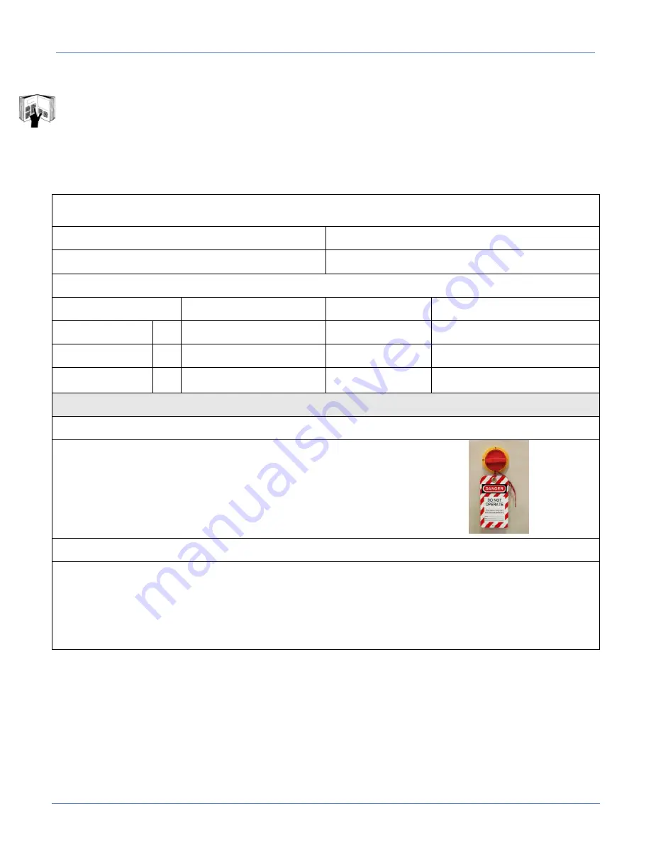
"Lockout/Tagout (LOTO)" refers to specific practices and procedures to safeguard employees from the
unexpected energization or startup of machinery and equipment, or the release of hazardous energy
during service or maintenance activities. This requires that a designated individual turns off and
disconnects the machinery or equipment from its energy source(s) before performing service or
maintenance and that the authorized employee(s) either lock or tag the energy-isolating device(s) to
prevent the release of hazardous energy and take steps to verify that the energy has been isolated
effectively. The following references provide information about the LOTO process.
Equipment Energy Control Procedure
Lockout/Tagout Program
Description:
Border Workstation
Model:
4300
Manufacturer:
Atlanta Attachment Co.
Location:
Energy
Location
Magnitude
Control Method
Electrical:
X Disconnect/Ctrl Box
220V
Lockout & Tag
Pneumatic:
X Main Regulator
90 PSI
Lockout & Tag
Gravity:
X Folder Assy, Knife Assy,
Transfer Clamp
Remember to Release All Stored Energy!
Shutdown Procedure:
1.
Inform all affected personnel that the machine will be in Lockout status.
2.
Turn the power and pneumatic disconnects to the OFF position.
3.
Fill out the tag with necessary information of the Lockout.
4.
Install the Lockout device.
5.
Verify all stored electrical energy has been released by pressing the power on button
. Also, use meter to test circuits in the electrical panel to insure stored energy is released there
as well.
Perform necessary maintenance, services and/or repairs.
Startup Procedure:
1.
Inform all affected personnel that the Lockout of this machine is being removed.
2.
Replace any guards or safety devices which may have been removed during maintenance.
3.
Remove the Lockout device and tag.
4.
Turn the power and pneumatic disconnects to the ON position.
5.
Push the green button on the back of the control panel to turn the machine on.
6.
Inform all affected personnel that the Lockout has been removed and that the machine is ready for normal production
operation.
Approved By: _______________________ Date: _________________________
Summary of Contents for 4300B
Page 2: ......
Page 28: ...Technical Manual Parts Lists 21 4 Create Edit Style ...
Page 59: ...Technical Manual Parts Lists 52 Parameter Selection Direct Selection ...
Page 60: ...Technical Manual Parts Lists 53 Changing Parameter values ...
Page 61: ...Technical Manual Parts Lists 54 Parameter Selection with the Keys ...
Page 73: ...Technical Manual Parts Lists 66 3 8 Troubleshooting 3 8 1 Efka Controller Error ...
Page 74: ...Technical Manual Parts Lists 67 3 8 2 Flow Chart EFKA Error E1 ...
Page 78: ...Technical Manual Parts Lists 71 ...
Page 80: ...Technical Manual Parts Lists 73 ...
Page 82: ...Technical Manual Parts Lists 75 ...
Page 86: ...Technical Manual Parts Lists 79 1961 800F Waste Assembly AAC Drawing Number 9002612 Rev 3 ...
Page 94: ...Technical Manual Parts Lists 87 ...
Page 96: ...Technical Manual Parts Lists 89 ...
Page 100: ...Technical Manual Parts Lists 93 ...
Page 102: ...Technical Manual Parts Lists 95 ...
Page 106: ...Technical Manual Parts Lists 99 ...
Page 108: ...Technical Manual Parts Lists 101 ...
Page 114: ...Technical Manual Parts Lists 107 ...
Page 115: ...Technical Manual Parts Lists 108 4300285 Encoder Assembly AAC Drawing Number 4300285 Rev 1 ...
Page 116: ...Technical Manual Parts Lists 109 ...
Page 118: ...Technical Manual Parts Lists 111 ...
Page 121: ...Technical Manual Parts Lists 114 ...
Page 123: ...Technical Manual Parts Lists 116 ...
Page 125: ...Technical Manual Parts Lists 118 ...
Page 127: ...Technical Manual Parts Lists 120 ...
Page 132: ...Technical Manual Parts Lists 125 4300 PD Pneumatic Diagram 125907B ...
Page 133: ...Technical Manual Parts Lists 126 4300 WD Wiring Diagram 125903A ...


