background image

Technical Manual & Parts Lists 

61 


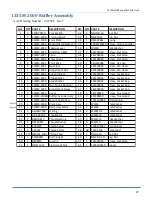
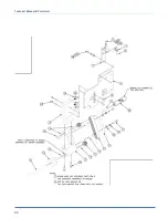
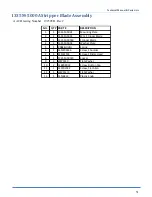
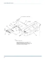
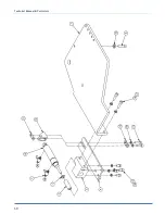
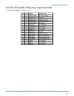
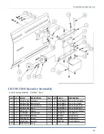
1335M-2200 Ruffler Mounting Angle Assembly 

AAC Drawing Number   192727C   Rev1 


NO.

QTY PART #

DESCRIPTION

1

1

1335M-2005

Mounting Angle

2

1

1335M-2017

Rod End

3

1

1335M-2027

Cylinder Mount

4

1

1335M-2028

Cylinder Support

5

1

1335M-2046

Nut Plate

6

1

A-2206A

Threaded Rod

7

2

AA198RA510

Flow Control

8

1

AAC8DP-.5

Air Cylinder

9

1

AAFBP-8C

Pivot Brkt

10

1

NNH10-32

Hex Nut

11

1

NNH10-32S

Hex Nut, Small

12

4

SSSC90024

Screw, Socket Cap

13

2

SSSC90032

Screw, Socket Cap

14

2

SSSC98040

Screw, Socket Cap

15

2

WWF8

Flat Washer

16

6

WWL8

Lock Washer

17

2

WWL10

Lock washer


Summary of Contents for 1335MDS

Page 1: ...Atlanta Attachment Company 362 Industrial Park Drive Lawrenceville GA 30046 770 963 7369 www atlatt com Technical Manual Parts Lists Model 1335MDS Revision 16 Updated Mar 7 2012 ...

Page 2: ......

Page 3: ...ies of these materials Patents Patents Pending The sale of this product does not sell or otherwise transfer any license or other rights under any U S Patent or other corresponding foreign patent This equipment is manufactured under one or more of the following patents 4 280 421 4 432 294 4 466 367 4 644 883 5 134 947 5 159 889 5 203 270 5 373 798 5 437 238 5 522 332 5 524 563 5 562 060 5 634 418 5...

Page 4: ...xes 13 Efka Control Boxes 13 Basic Machine Operation Panel Mode 14 Loading the Gusset Roll and Unwinder 14 Loading and Adjusting the Folder 14 Adjusting the Edge Guide 15 Sewing the Panel 15 Adjusting the Corner Ruffles 15 Finishing the Panel 15 Basic Machine Operation Frames Mode 16 Setting the Switches 16 Setting the Thumbwheels 16 Loading the Flange Roll and Folder 16 Sewing the Frame 16 Finish...

Page 5: ...ly 33 11337AT Air Table Assembly 35 A 2216K5 16 Flat Folder 5 16 x 6 37 A 2216M 5 16 Book Folder 5 16 x 18 39 1334 2600 Tension Assembly 41 1335MD 10 Sewing Head Modification 43 1335M 120 Puller Drive Assembly 45 1335M 2000 Ruffler Assembly 47 1335MDS 3000 Puller Assembly 49 1335M 5000A Stripper Blade Assembly 51 1335MD 6000 Footlift Assembly 53 1335M 9500 Stepper Box Assembly 55 1337A 160 Air Tab...

Page 6: ...Technical Manual Parts Lists 1335M PD Pneumatic Diagram 70 1335MDS PD Pneumatic Diagram 71 1335MDS WD Wiring Diagram 72 1335MDS WD1 Wiring Diagram 73 1335MDS WD2 Connection Diagram 76 ...

Page 7: ...clude A list of recommended spare parts Instruction Manual s for components made by other manufacturers The layout and installation diagram containing information for installation Intended Use Our machines are designed and built in line with the state of the art and the accepted safety rules However all machines may endanger the life and limb of their users and or third parties and be damaged or c...

Page 8: ... work on the machine is only carried out by reliable persons who have been appropriately trained for such work either within the company by our field staff or at our office and who have not only been duly appointed and authorized but are also fully familiar with the local regulations Work on the machine should only be carried out by skilled personnel under the management and supervision of a duly ...

Page 9: ...airing safety are observed in the machine or its mode of operation such as malfunctions faults or changes in the machine or tools appropriate steps must be taken immediately the machine switched off and a proper lockout tagout procedure followed The machine should be examined for obvious damage and defects at least once per shift Damage found shall be immediately remedied by a duly authorized pers...

Page 10: ...ny obstructions whatsoever is essential for safe operation of the machine The floor should be level and clean without any waste The workplace should be well lit either by the general lighting or by local lights Emergency STOP The emergency STOP buttons bring all machine movements to a standstill Make sure you know exactly where they are located and how they work Try them out Always ensure easy acc...

Page 11: ... so that it cannot be switched on again without authorization In practice this may mean that the technician electrician and operator all attach their own padlock to the master switch simultaneously so that they can carry out their work safely Locking extension plates should be available for multiple locks if required The primary purpose for a lockout tagout procedure is to protect workers from inj...

Page 12: ...hen transporting the machine or assemblies in a crate ensure that the ropes or arms of a forklift truck are positioned as close to the edge of the crate as possible The center of gravity is not necessarily in the middle of the crate Note the accident prevention regulations safety instructions and local regulations governing transport of the machine and its assemblies Only use suitable transport ve...

Page 13: ... Do not use any corrosive cleaning agents Use lint free rags Retighten all screw connections that have to be loosened for the maintenance and repair work Any safety mechanisms that have to be dismantled for setting up maintenance or repair purposes must be refitted and checked immediately after completing the work Maintenance Care Adjustment The activities and intervals specified in the Instructio...

Page 14: ...fault develops in the electrical power supply The electrical equipment of our machines must be checked at regular intervals and any defects found must be remedied immediately If it is necessary to carry out work on live parts a second person should be on hand to operate the emergency OFF switch or master switch with voltage release in the event of an emergency The working area should be cordoned o...

Page 15: ...stands this manual before operating this equipment It is also the owner s responsibility to make certain that the operator is a qualified and physically able individual properly trained in the operation of this equipment Specific safety warning decals are located on the equipment near the immediate areas of potential hazards These decals should not be removed or obliterated Replace them if they be...

Page 16: ...0 RPM Needle Standard Schmetz TVx7 Size 16 Stitch Density 6 SPI Installation Setup Provide a 220VAC single phase 5 Amp electrical drop and 1 4 air supply line 80 PSI Remove any shipping straps from machine Mount and adjust the Guide Roller Assembly See Fig 1 Check the oil level in the oil pan To check oil unclamp the puller motor bracket and lean the puller motor back See Fig 2 Then lean the head ...

Page 17: ...foot switch must be released and pressed again to continue the cycle The Manual Ruffle pushbutton turns on one ruffle cycle and is also the Reset button for the automatic cycle Pushing this button once will turn on the ruffle cycle for one ruffle Pushing it a second time will reset the automatic program and cause the ruffle hardware to reset and go to its Home position Use this button to reset the...

Page 18: ... stop the panel so that when the corner turn is finished the right edge of the panel is flush against the edge guide If after turning the corner the right edge of the panel is to the left of the edge guide decrease the stitch count to stop the panel sooner If after turning the corner the right edge of the panel is to the right of the edge guide increase the stitch count to stop the panel closer to...

Page 19: ...this switch on all the time Note The on off switch only switches one line and does not make the box safe to work on Always disconnect the main power cord before servicing the control box Efka Control Boxes The sewing machine is powered by the Efka motor controller located under the table It has its own on off switch which should be left on all the time It also has some small buttons and LED s on t...

Page 20: ...usset as you continue to load the machine If the Unwinder runs in the wrong direction flip the direction switch located on the main control box Feed the gusset over the top rollers and down to the folder with the good side toward the sewing head When making continental foundations the good side will face the operator Loading and Adjusting the Folder Feed the gusset through the top portion of the f...

Page 21: ...ear the presser foot and your left hand about 1 foot to the left on the panel Treadle forward and allow the machine to make the first ruffle sewing straight Begin to rotate the panel as the rest of the ruffles are formed Try to turn an equal amount with each ruffle so that when the ruffles are complete the panel has turned 90 degrees and the right edge of the panel is resting against the left edge...

Page 22: ...art to cross reference between the different frame sizes and the actual numbers set in the thumbwheels Loading the Flange Roll and Folder Load the front roll holder with the flanging required and adjust the edge guides and tension rods as necessary Load the gusset through the folder under the encoder roller and under the presser foot with at least 1 of material past the needle Be sure the sensor a...

Page 23: ...cal tape to prevent accidental short circuit and damage to the control box The voltage at the plug is only 5 volts Install the large folder with the slots all the way to the left Load the gusset material with the good side down at the presser foot Adjust the folder and edge guides for the stitch margin desired Adjust the overhead roller to keep the gusset aligned with the folder Continental founda...

Page 24: ...ssure should be set very light so that the ruffling blade can feed under the foot while ruffling The Efka motor should be set for stopping needle down at neutral treadle to help hold the ruffle in place while turning the corners The auxiliary foot pressure cylinder should be set to provide added foot pressure while sewing straight Ruffler Drive Set the Ruffler blade position left to right The slot...

Page 25: ...e Daily Clean machine at the end of every shift Clean lint etc from the Looper bobbin area on the sewing head Remove any threads wrapped around moving parts of the handwheel puller and ruffler Wipe all photo eye lenses with clean nonabrasive dry cloth Use blow off hose to get rid of excess lint thread and other clippings Follow manufactures recommendations and guidelines for daily maintenance and ...

Page 26: ...ase this value to slow down sewing head until measured speed matches speed set with parameter 111 For Yamato and Pegasus setting should be 100 for Rimoldi setting should be 124 Front panel LED s Programming Instructions LED 1 Off 1 Power on holding down the P button till COD is displayed LED 2 Off 2 Press once and enter the number 311 LED 3 Off 3 Press E once and 2 0 0 is displayed this is a param...

Page 27: ...Technical Manual Parts Lists 21 1335M Folder Spacer Reference Chart ...

Page 28: ...the reflective tape turn the GAIN screw counter clockwise until the red LED indicator is off Then turn the GAIN screw clockwise until the LED indicator comes on Then turn the GAIN screw one full turn clockwise The LED indicator should be blinking slowly Cover the eye so that the sensor cannot see the reflective tape and the LED should go off Reflective Tape Maintenance Use a soft cloth for cleanin...

Page 29: ...a Attachment Company In addition to any confidentiality and non disclosure obligations that currently exist between you and Atlanta Attachment Company your use of these materials serves as an acknowledgment of the confidential and proprietary nature of these materials and your duty not to make any unauthorized use or disclosure of these materials ...

Page 30: ...Technical Manual Parts Lists 24 ...

Page 31: ...NNH3 8 16 Hex Nut 7 2 SSHC01048 Screw Hex Cap 8 2 SSHC25192 Screw Hex Cap 9 2 WWFS1 4 Flat Washer 10 4 WWFS3 8 Flat Washer 11 2 WWL3 8 Lock Washer 12 1 11337AT Air Table Assy 13 1 1335081 Shelf Support 14 3 SSZH 10064 Screw Sheet Metal 15 1 A 2216M5 16 Flat Folder 16 1 778A 12 Roll Holder 17 1 1334 2600 Tension Assy 18 1 1335M 1002 Edge Guide 19 1 1335M 2500 Encoder Assy 20 1 SSBK01160 Carriage Bo...

Page 32: ...Technical Manual Parts Lists 26 ...

Page 33: ...AR Parameter List 12 1 1335M PD Pneumatic Diagram 13 1 1335MDS WD Wiring Diagram 14 1 1335MDS WD1 Wiring Diagram 15 3 WWFS1 4 Flat Washer 16 10 SNTVX7X110 Needle Size 110 17 2 SSBC98032 Screw Button Cap 18 3 SSSC98040 Screw Socket Cap 19 3 SSHC01048 Screw Hex Cap 20 1 SSHC20064 Screw Hex Cap 21 1 WWL5 16 Lock Washer 22 4 SSZH 10048 Screw Sheet Metal 23 3 WWL1 4 Lock Washer 24 3 WWL10 Lock Washer 2...

Page 34: ...Technical Manual Parts Lists 28 ...

Page 35: ...198 503 Air Gauge 19 1 AA198 5102 Regulator 20 3 AA198 RP3 Regulator 21 3 EEDC2X2 Duct Cover 22 3 EEDF2X2 Wire Duct 23 2 FFSM312LVQ Electric Eye 24 1 AAQMT 4 8 Quick T 25 3 AAQMC 5 4 Quick Connect 26 1 K CB600 Motor Starter 27 4 MMFB4444 Rubber Foot 28 4 NNH1 2 13 Hex Nut 29 3 NNH5 16 18 Hex Nut 30 18 WWFS10 Flat Washer 31 2 AAF3 16 Plastic Clamp 32 3 WWF5 16 Flat Washer 33 4 SSPS98032 Screw Pan H...

Page 36: ...Technical Manual Parts Lists 30 ...

Page 37: ...Screw Hex Cap 12 1 1335M 4100A Frame Weldment 36 2 SSHC25160 Screw Hex Cap 13 1 1961 365 Bearing Block 37 2 WWL3 8 Lock Washer 14 1 1961 370 Nut Plate 38 5 WWL10 Lock Washer 15 1 23218DM Motor Assy 39 2 SSPS70048 Screw Pan Head 16 1 265155A Eye Holder 40 6 SSSC01064 Screw Socket Cap 17 1 1335 837 Rod 1 2 U 42 5 SSSC98024 Screw Socket Cap 18 1 A 202 1809 18 Disc 43 3 SSZS93032 Screw Sheet Metal 19 ...

Page 38: ...Technical Manual Parts Lists 32 ...

Page 39: ...3 1 1335 835A Bent Rod 1 2 x 4 x 26 4 1 8732 0576 Rod 1 2 x 9 5 1 1335 319B Rod Clamp 1 2 6 3 28201 Cross Block 7 1 1335 838 Roller 2 x 18 5OL 8 1 1335 814D Roller 2 x 25 5OL 9 2 TTH32425 Threaded Handle 10 1 SSSS10048 Socket Cap Screw 11 1 8732 1536 Rod 1 2 x 24 12 1 CCCL8F Clamp Collar 13 2 SSSC95048 Screw Socket Cap 14 2 TTH32426 Threaded Handle 15 1 28201A Cross Block ...

Page 40: ...Technical Manual Parts Lists 34 ...

Page 41: ... 1 1 1335081 Support Shelf 2 AR 1337023 BRKT Table Ruffler 3 AR 1337024 Air Table Mount 4 2 1337A 0168B Retainer BRKT 5 1 1337A 160 Air Table Assy 6 1 1337A 175C Air Table Shelf 7 2 NNK5 16 18 Kep Nut 8 6 SSHC10064 Hex Head 9 3 SSZH 10048 Sheet Metal Screw 10 8 WWFS5 16 Flat Washer 11 4 WWL5 16 Lock Washer Page 57 ...

Page 42: ...Technical Manual Parts Lists 36 ...

Page 43: ...g Nut 2 2 A 2216D22 T Nut 3 2 A 2216D53 Spacer 1 4 4 2 A 2216G29 Spacer 5 16 5 1 A 2216K02 Folder Plate 6 2 A 2216K04 Folder Top 7 2 A 2216D34 Guide 5 16 8 4 NNK10 32 Kep Nut 10 4 WWL10 Lock Washer 11 2 SSSC98040 Screw Socket Cap 12 4 SSBC98048 Screw Button Cap 13 8 WWFS10 Flat Washer 14 2 SSBC98064 Screw Button Cap 15 1 1335A 302 Label ...

Page 44: ...Technical Manual Parts Lists 38 ...

Page 45: ...er 5 16 4 1 A 2216M02 Folder Plate 5 2 A 2216M04 Folder Top 6 1 A 2216D34 Guide 5 16 7 4 NNK10 32 Kep Nut 8 1 SSBC98064 Screw Button Cap 9 4 SSBC98048 Screw Button Cap 10 5 WWFS10 Flat Washer 11 2 WWL10 Lock Washer 12 1 A 2216G34 Spacer 9 16 13 1 A 2216D39 Guide 9 16 14 2 SSBC98056 Button Cap Screw 15 2 SSBC98072 Button Cap Screw 16 1 A 2216G30 Spacer 7 16 17 1 A 2216D37 Guide 7 16 ...

Page 46: ...Technical Manual Parts Lists 40 ...

Page 47: ...600 Tension Assembly AAC Drawing Number 192511B Rev1 NO QTY PART DESCRIPTION 1 1 1335 316B Bent Rod 2 1 1335 318 Rod Slide Arm 3 1 1335 319 Rod Clamp Arm 4 1 1335 320B Straight Rod 5 2 TTH34311 Threaded Handle 6 1 SSHC95048 Screw Socket Cap ...

Page 48: ...Technical Manual Parts Lists 42 ...

Page 49: ...2862C Rev1 NO QTY PART DESCRIPTION 1 1 1335M 3009 Brkt 2 1 B1122552000 Gasket 3 2 SSFC90048 Screw Flat Allen 4 3 SSM50267 Screw Fillister Head 5 1 22100 019 Sync Adapter 6 1 1278 6364 Tape Mount Disc 7 1 SJUKI 481U Sewing Head 8 1 M1191 019 Foot Ruffler SN NF 9 1 CCCL4F Clamp Collar 1 4 in ...

Page 50: ...Technical Manual Parts Lists 44 ...

Page 51: ...DIFIED 13 1 CCCL6F CLAMP COLLAR 3 8 14 1 GG100XL037 BELT GEAR 1 5P 3 8W 15 1 MM741 3A HINGE 3 X 3 STANLEY 16 1 MM8096307 CLAMP 17 1 NNH1 4 20 1 4 20 HEX NUT 18 4 NNH10 32 HEX NUT 10 32 REG 19 2 PP24XLB37M1 PULLEY GEAR 1 5 PITCH 20 1 SSFC01160 1 4 20 X 2 1 2 FLAT CAP 21 2 SSFC98032 10 32 X 1 2 FLAT ALLEN CAP 22 2 SSHC01160 1 4 20 X 2 1 2 HHCS 23 3 SSPS80024 6 32 X 3 8 LG PAN HD 24 4 SSSC90040 8 32 ...

Page 52: ...Technical Manual Parts Lists 46 ...

Page 53: ...er 44 2 SSSC90024 Screw Socket Cap 14 1 1335M 2038 Stop Washer 45 4 SSSC90032 Screw Socket Cap 15 1 1335M 2039 Nut Spring Retainer 46 4 SSSC98032 Screw Socket Cap 16 1 1335M 2040 Adjustment Screw 47 5 SSSC98048 Screw Socket Cap 17 1 1335M 2042 Cover 48 5 SSTS90024 Screw Truss Head 18 1 1335M 2100A Ruffler Cylinder Assy 49 2 SSTS98040 Screw Truss Head 19 1 1335M 2200 Mount Angle Assy 50 1 TTCL1APPK...

Page 54: ...Technical Manual Parts Lists 48 ...

Page 55: ...Sensor Brkt 10 2 1535 241 Transfer Spacer 11 2 350196 Gear Pulley 12 1 3514 3CU Fluted Roller 13 4 3517 Thrust Washer 14 2 AA198RA510 Flow Control 15 1 AACXSM2020 Air Cylinder 16 1 CCCL6F Clamp Collar 17 1 GG110XL75U Gear Belt 18 3 WWL10 Lock Washer 19 2 WWL1 4 Lock Washer 20 1 SSPS50032 Screw Pan Head 21 2 SSSC01064 Screw Socket Cap 22 3 SSSC98024 Screw Socket Cap 23 2 SSSC98064 Screw Socket Cap ...

Page 56: ...Technical Manual Parts Lists 50 ...

Page 57: ...ng Plate 2 1 1335M 5002 Mnt Stripper Blade 3 1 1335M 5003B Stripper Blade 4 1 1335M 5004 Washer Plate 5 1 RRBEEHIVEH Spring 6 1 SSM200246 Screw Shoulder 7 4 SSM22593 Screw Fillister Head 8 1 1335M 5003C Spacer 9 2 WWFS10 Flat Washer 10 2 SSBC98032 Screw Button Cap 11 1 SSFC01032 Screw Flat Allen 12 1 WWFS1 4 Flat Washer 13 1 SSMBK13 Plastic Knob ...

Page 58: ...Technical Manual Parts Lists 52 ...

Page 59: ...ified 3 1 1335M 6002 Shaft 4 1 32006524 Pivot Mnt Brkt 5 2 AA198RA508 Flow Control 6 1 AAC6DP 2 Air Cylinder 7 1 AAFBP 11C Pivot Brkt 8 1 BBAW 5Z Rod End 9 1 CCCL5F Clamp Collar 10 1 NNH1 4 20 Hex Nut 11 1 SSAS020032 Screw Allen Shoulder 12 2 SSBC98016 Screw Button Cap 13 2 SSSC98024 Screw Socket Cap 14 2 WWL10 Lock Washer 15 2 WWFS10 Flat Washer 16 1 NNJ5 16 24 Jam Nut ...

Page 60: ...Technical Manual Parts Lists 54 ...

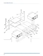
Page 61: ...Y PART DESCRIPTION 1 2 1335M 9010 Step Box Brkt 2 2 1335M 9011 Shelf Motor Box 3 2 1335M 9012 Mnt Ctrl Box 4 1 AP 28 800C Control Box 5 1 AP 28 800Y1 Stepper Box 6 2 EE37F3312 Power Cord 7 8 MMSLD ECH Rubber Bumper 8 8 SSFC80032 Screw Flat Allen 9 12 SSPP98032 Screw Pan Phillips 10 12 WWL10 Lock Washer ...

Page 62: ...Technical Manual Parts Lists 56 ...

Page 63: ... WELDMENT LEG TABLE 5 1 1337A 150 AIR TABLE ASSY 6 1 K 235 CONNECTOR ROMEX 1 2 7 4 MMFB4444 FOOT RUBBER 8 4 NNH1 2 13 NUT HEX 1 2 13 9 20 SSHC01048 1 4 20 X 3 4 HEX CAP 10 16 SSHC10064 5 16 18 X 1 HHCS 11 16 SSZH 10032 SCREW SHT METAL HEX 10 12 16 WWF1 4 WASHER FLAT 1 4 COM 13 4 WWFS1 4 WASHER FLAT SAE 1 4 14 16 WWFS5 16 WASHER FLAT SAE 5 16 15 20 WWL1 4 WASHER LOCK 1 4 16 16 WWL5 16 WASHER LOCK 5...

Page 64: ...L BLOWER INLET 13 2 SSSC90016 8 32 X 1 4 SOC CAP SC 4 1 1337136 COVER CAPACITOR 14 3 SSSCM6X16 M6X16 SOC CAP SCREW 5 1 1337137 SPACER 15 1 TT5802 TERMINAL RING 10 STUD 6 2 EERB44 STA KON WIRE JOINT 16 1 TTH6324K170 HANDLE THR D M6 X 16MM 7 1 FF19509 CABLE 3 COND 18 AWG SJTOW 17 2 WWF8 WASHER FLAT 8 8 1 FFHBL4570C PLUG 2P 3W GROUNDING 18 12 WWFS5 16 WASHER FLAT SAE 5 16 9 1 MM1TDT3 BLOWER 230V 559C...

Page 65: ...M 2002C Stripper Blade 12 3 SSSC80064 Screw Socket Cap 3 1 1335M 2003A Cylinder Mount Plate 13 8 SSSCM4X10 Screw Socket Cap 4 1 1335M 2033 Stop Mount 14 3 WWL6 Lock Washer 6 1 1335M 5004 Washer Plate 15 4 WWL8 Lock Washer 7 2 AA198RA510 Flow Control 16 2 NNW10 32 Wing Nut 8 1 AACMXH1025 Air Cylinder 17 2 WWL10 Lock Washer 9 1 NNH8 32 Hex Nut 18 1 1335M 2048 Stud Plate 10 1 SSFC90064M Screw Flat Al...

Page 66: ...Technical Manual Parts Lists 60 ...

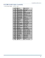
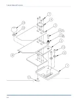
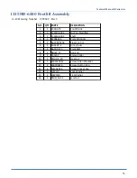
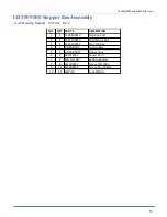
Page 67: ... 2027 Cylinder Mount 4 1 1335M 2028 Cylinder Support 5 1 1335M 2046 Nut Plate 6 1 A 2206A Threaded Rod 7 2 AA198RA510 Flow Control 8 1 AAC8DP 5 Air Cylinder 9 1 AAFBP 8C Pivot Brkt 10 1 NNH10 32 Hex Nut 11 1 NNH10 32S Hex Nut Small 12 4 SSSC90024 Screw Socket Cap 13 2 SSSC90032 Screw Socket Cap 14 2 SSSC98040 Screw Socket Cap 15 2 WWF8 Flat Washer 16 6 WWL8 Lock Washer 17 2 WWL10 Lock washer ...

Page 68: ...Technical Manual Parts Lists 62 ...

Page 69: ...k 4 1 1335M 2010 Pivot Block 5 1 1335M 2011 Pivot Shaft 6 2 1335M 2012 Side Link 7 1 1335M 2013 Link Shaft 8 1 1335M 2014 Link Shaft 9 2 1335M 2015 Link Yoke 10 2 BBNTA815 Thrust Bearing 11 4 BBTRA815 Thrust Washer 12 6 MM8407A134 E Ring 13 1 NNE3 8 16 Elastic Lock Nut 14 1 SSAS032096 Socket Shoulder Screw 15 2 SSSC98048 Screw Socket Cap 16 2 IIS012X064 Spring Pin 17 1 WWFS3 8 Flat Washer ...

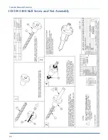
Page 70: ...Technical Manual Parts Lists 64 1335M 2400 Ball Screw and Nut Assembly 9000982 ...

Page 71: ...e Mount 12 4 SSPS98024 Screw Pan Head 3 1 1335M 2503 Tension Plate 13 6 SSSC98032 Screw Socket Cap 4 1 1335M 2504 Cover 14 2 SSSS98016 Screw Socket Set 5 1 1981A 271 Wheel 15 1 SSTS95128 Screw Truss Slotted 6 1 A 2216K03 Folder Plate 16 3 WWFS10 Flat Washer 7 1 EEH1 096 HS Encoder 17 2 WWL10 Lock Washer 8 1 IID016X128 Dowel 18 2 WWL6 Lock Washer 9 3 NNH10 24 Hex Nut 19 2 BBTT601 Thrust Washer 10 1...

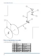
Page 72: ...ll Holder Assembly AAC Drawing Number 298772C Rev0 NO QTY PART DESCRIPTION 1 2 785 A9 12 Disc 2 1 780 101 Support Rod 3 1 A U Connector 4 1 273 4 407A Support Rod 5 1 AA192 6A1 Mount 6 4 SSZH 10064 Screw Sheet Metal 7 1 TTH32425 Threaded Handle ...

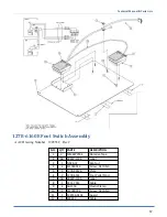
Page 73: ...ART DESCRIPTION 1 3 MM6970T64 Abrasive Tape 2 AR 3844P 119B Label 3 1 NNK6 32 Kep Nut 4 4 SSFC80016 Screw Flat Allen 5 1 1278 5051B Plate 6 2 1278 6161 Foot Pedal Mod 7 AR 3844P 119A Label 8 1 0211 705C Cable 9 1 AAF3 8 Plastic Clamp 10 1 SSFC80024 Screw Flat Allen 11 1 132556 010E Guard 12 1 EE8442 Cable ...

Page 74: ...Technical Manual Parts Lists 68 ...

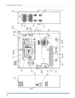
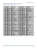
Page 75: ...SHC01032 Screw Hex Cap 44 1 1335MDS LAB Label 14 4 SSPP80016 Screw Pan Phillips 45 4 AAF1 8 Plastic Clamp 15 2 SSPS90080 Screw Pan Head 46 1 AP 28 610U Cable 16 1 AAE211E 4 Solenoid Assy 47 1 AP 28 612L Cable 17 1 1987 513A Cable 48 1 FF250LA40A Varistor 18 3 WWFS10 Flat Washer 49 3 FFRK44T 4 Cable 19 4 FF67F4078 Threaded Spacer 50 1 1987 513B Cable 20 4 FF89F2609 Spacer 51 1 FF313005 Fuse 5A Slow...

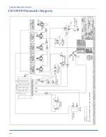
Page 76: ...Technical Manual Parts Lists 70 1335M PD Pneumatic Diagram 125618C ...

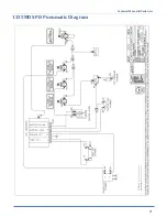
Page 77: ...Technical Manual Parts Lists 71 1335MDS PD Pneumatic Diagram 125670C ...

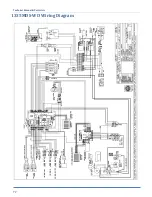
Page 78: ...Technical Manual Parts Lists 72 1335MDS WD Wiring Diagram 125650C ...

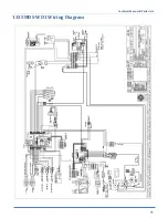
Page 79: ...Technical Manual Parts Lists 73 1335MDS WD1 Wiring Diagram 125573B ...

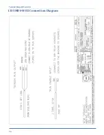
Page 80: ...Technical Manual Parts Lists 74 1335MDS WD2 Connection Diagram 125576B ...

Page 81: ...Technical Manual Parts Lists 75 ...

Page 82: ...ent upon proper application installation and maintenance AAC Limited Warranty may not be changed or modified and is not subject to any other warranty expressed or implied by any other agent dealer or distributor unless approved in writing by AAC in advance of any claim being filed What Is Covered Electrical components that are not included within the Serial Bus System that fail due to defects in m...

Page 83: ... AAC no puede ser cambiado o modificado y no está sujeto a cualquier otra garantía implicado por otro agente o distribuidor menos al menos que sea autorizado por AAC antes de cual quier reclamo Lo Que Está Garantizado Componentes eléctricos que no están incluidos dentro del sistema Serial Bus que fallen por defectos de materiales o de fabricación que han sido manufacturados por AAC son garantizado...

Page 84: ...Atlanta Attachment Company 362 Industrial Park Drive Lawrenceville GA 30046 770 963 7369 www atlatt com Printed in the USA ...

Reviews: